


Verification and Calibration - B
61
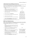
Voltage Programming and Measurement Accuracy
This test verifies the voltage programming, GPIB measurement, and front panel meter functions. Values
read back over the GPIB should be the same as those displayed on the front panel.
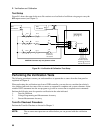
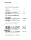
Figure B-1 shows the setup. Measure the ac output voltage directly at the output terminals. If you are
verifying a three-phase source, sart by verifying output phase 1.
Action Normal Result
1. Make sure the ac source is turned off. Connect the DVM and ratio
transformer as shown in the test setup in Figure B-1.
2. Turn on the ac source with no load. In the Output menu, execute the
*RST command to reset the unit to its factory default state.
*RST
3. Program the output voltage to 150 volts and set the output current
limit to its maximum value.
CV annunciator on.
Output voltage near 0.
Output current near 0.
4. Enable the output by pressing
Output On/Off. Output voltage near 150 V.
5. Record voltage readings at the DVM
1
and on the front panel display. Readings within low voltage
limits specified in table B-2.
6. Program the output voltage to 300 volts. Output voltage near 300 V.
7. Record voltage readings at the DVM
1
and on the front panel display. Readings within high voltage
limits specified in table B-2.
8.
If you are verifying a 3-phase source, repeat steps 1 through 7 for
phases 2 and 3. Press
Phase Select to select the next phase.
Readings within specified High
range limits (300 V/1 kHz).
1
Multiply the DVM reading by the transformer ratio if a ratio transformer is used.
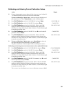
RMS Current Readback Accuracy
This test verifies the current readback. Use the appropriate current shunt with the accuracy specified in
table B-1. Use wire of sufficient size to carry the maximum rated current of the ac source (see table 2-1).
If you are verifying a 3-phase source, start by verifying phase 1.
Action Normal Result
1. Turn off the ac source. Connect the load resistor, current shunt, and
the DVM across the current shunt as shown in Figure B-1. Use the
following load resistor values:
Agilent 6814B = 7.5
Ω
; Agilent 6834B = 15
Ω
; Agilent 6843A = 5
Ω
2. Turn on the ac source. In the Output menu, execute the *RST
command to reset the unit to its factory default state.
*RST
3. Program the output voltage to 100 volts and set the current limit as
follows:
Agilent 6814B = 10 A; Agilent 6834B = 5A; Agilent 6843A = 15A
Then enable the output by pressing Output On/Off.
CC annunciator on. Output current
near 10 A for Agilent 6814B
near 5 A for Agilent 6834B
near 15A for Agilent 6843A
4. Record the DVM voltage reading and calculate the rms current.
Divide the DVM reading by the current monitor resistor value.
Record the front panel reading.
Difference between the measured
output current and front panel
readings are within specified limits.
5.
If you are verifying a 3-phase source, repeat steps 1 through 4 for
phases 2 and 3. Press
Phase Select to select the next phase.