


59
B
Verification and Calibration
Introduction
This appendix includes verification and calibration procedures for the Agilent 6814B/6834B/6843A AC
Power Solutions. Instructions are given for performing the procedures either from the front panel or from
a controller over the GPIB.
The verification procedures do not check all the operating parameters, but verify that the ac source is
performing properly. Performance Tests, which check all the specifications of the ac source, are given in
the applicable ac source Service Manual.
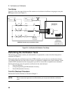
Because the output of the ac source must be enabled during verification or calibration, proceed with
caution, since voltages and currents will be active at the output terminals.
Important Perform the verification procedures before calibrating your ac source. If the ac source
passes the verification procedures, the unit is operating within its calibration limits and
does not need to be recalibrated.
WARNING LETHAL VOLTAGES. Ac sources can supply 424 V peak at their output. DEATH
on contact may result if the output terminals or circuits connected to the output are
touched when power is applied. These procedures must be performed by a qualified
electronics technician or engineer trained on this equipment.
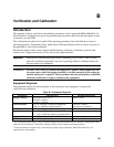
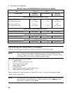
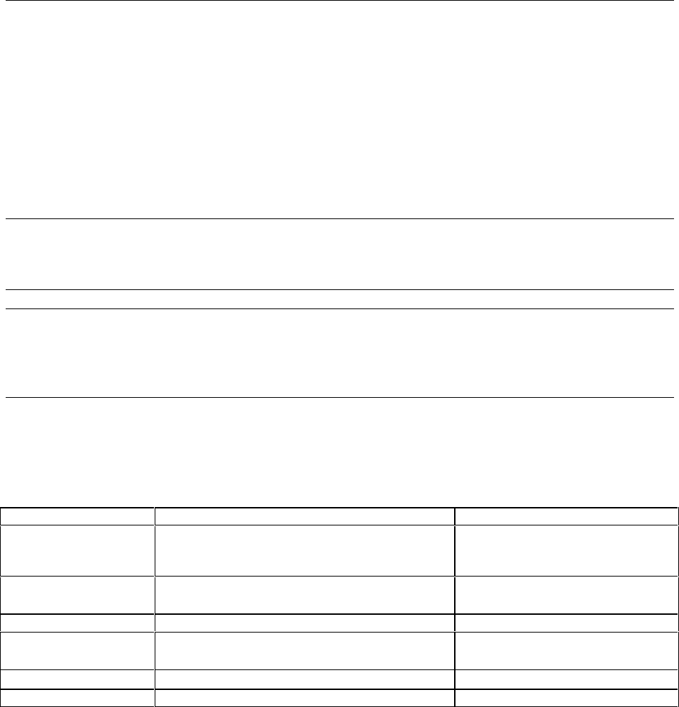
Equipment Required
The equipment listed in the following table, or the equivalent to this equipment, is required for
verification and calibration.
Table B-1. Equipment Required
Equipment Characteristics Recommended Model
Digital Voltmeter
Resolution: 10 nV @ 1 V
Readout: 8.5 digits
Accuracy: >20 ppm
Agilent 3458A
Current Monitor
1
0.01
Ω
,
±
200 ppm, (Agilent 6814B/6834B)
0.001
Ω
,
±
200 ppm, (Agilent 6843A)
Guildline 7320/0.01
Norma Gerts Instruments
Ratio Transformer
2
30:1 ratio, 50 ppm, 45 Hz to 1 kHz
Load Resistors
2 − 15 Ω, > 1.5 kW (Agilent 6814B/6834B)
1 − 5 Ω, > 4.8 kW non-inductive (Agilent 6843A)
Impedance Resistor
1 Ω, 100 Watts min. (Agilent 6843A only)
GPIB Controller
Full GPIB capabilities HP Series 200/300 or equivalent
1
The 4- terminal current shunt is used to eliminate output current measurement error caused by voltage drops in the
load leads and connections. Connect the voltmeter directly to these current-monitoring terminals.
2
A ratio transformer is required only when verifying output voltage readback to MIL-STD-45662A 4:1 test
equipment ratio requirements.