


Document 50934 Rev B 5/15/00 PN 50934:B
62
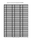
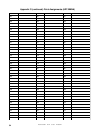
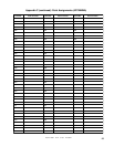
The ADT-UDACT is capable of reporting up to 2,040 points when used with the ADT-MNNA. The first 568 points can
be programmed using the Type Mode feature (refer to Section 4.2). All points greater than 568 can be transmitted only
as fire alarm points. For the ADT-UDACT to report a supervisory point to the central station, both the FACP and the
ADT-UDACT must have the point programmed as supervisory. Failure to program the panel or ADT-UDACT correctly
will result in a fire alarm signal being transmitted to the central station.
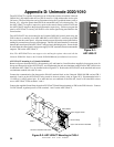
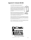
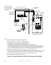
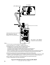
The ADT-UDACT may be mounted in the ADT-MNNA control panel using the CHS-4 chassis or remotely in an ADT-
ABS8RF or ADT-UBS-1 enclosure up to 6,000 feet away from the control panel. All power must be removed from the
control panel before making any connections to prevent circuit damage. The EIA-485 serial interface is connected between
the control panel and ADT-UDACT using twisted, shielded pair wire. Power should be wired from the control panel's
main power supply 24 VDC (nominal) filtered, nonresettable output to TB1 on the ADT-UDACT.
Note: The ADT-UDACT does not support voice and burglar options when used with the ADT-MNNA. Refer to the ADT-
MNNA Manual for additional restrictions.
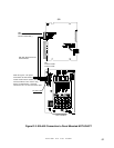
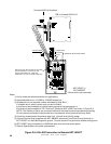
ADT-UDACT mounting in an ADT-MNNA
Remove all power from the ADT-MNNA by disconnecting AC and batteries. Install the three supplied nylon support
posts for the top and bottom left of the ADT-UDACT, one aluminum/nylon and one aluminum standoff in the CHS-4
chassis slot in which the ADT-UDACT is to be installed. Position the ADT-UDACT on the standoffs and secure on
aluminum standoff with a #6-32 screw.
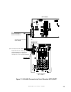
Connect the communication line between the EIA-485 terminal block on the ADT-MNNA and TB-1 terminals 3 and 4 on
the ADT-UDACT being certain to observe polarity (refer to Figure F-1). Recommended wire is 12 AWG to 18 AWG
twisted pair. If no other devices are connected to the EIA-485, install a 120 ohm EOL resistor across ADT-UDACT TB1
terminals 3 and 4.
Connect the supplied Ground Strap from the ADT-UDACT Earth Ground terminal on TB3 to the CHS-4 chassis. Connect
24 VDC filtered power to TB1 terminals 1 and 2 on the ADT-UDACT.
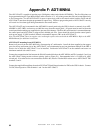
Appendix F: ADT-MNNA