


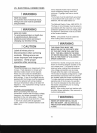
I WARNING
HIGH
VOL
TAGEI
TO
AVOID THE RISK OF INJURY,
ELECTRICAL
SHOCK
OR
DEATH, THE
FURNACE MUST
BE
ELECTRICALLY
GROUNDED IN ACCORDANCE WITH
LOCAL
CODES
OR
IN THEIR
ABSENCE, WITH
THE
LATEST
EDITION OF THE NATIONAL
ELECTRIC CODE.
To
ensure proper unit grounding, the ground
wire should run from the furnace ground
screw located inside the furnace junction
box all the way back to the electrical panel.
NOTE: Do not use oil piping as an
electrical ground. To confirm proper unit
grounding, turn
off
the electrical power and
perform the following check:
1.
Measure resistance between the
neutral (White) connection and a
suitable chassis ground.
2.
Resistance should measure 10 ohms or
less.
This furnace is equipped with a blower door
interlock switch which interrupts unit voltage
when the blower door is opened for
servicing. Do not defeat this switch.
24
Volt
Thermostat
Wiring
NOTE:
Wire
routing must not interfere with
circulator blower operation, filter removal, or
routine maintenance.
Low voltage connections can be made
through either the right or left side panel.
Thermostat wiring entrance holes are
located adjacent to the junction box
locations in the blower compartment.
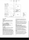
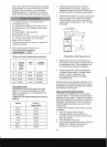
Thermostat
Diagram
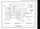
This furnace is equipped with a 40
VA
transformer to facilitate use with most
cooling equipment. Consult the wiring
diagram, located on the blower
compartment door, for further details,
of
115
Volt and 24 Volt wiring.
VIII. CONDENSATE DRAIN LINES
& DRAIN TRAP
GENERAL
A condensing oil-fired furnace achieves its
high level
of
efficiency by extracting almost
all
of
the heat from the products
of
. combustion and cooling them to the point
where condensation takes place.
The condensate which is generated must
be piped to an appropriate drain location.
The furnace's drain hoses may exit either
the right
or
left side
of
the furnace.
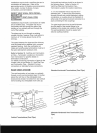
In horizontal installations, the drain hoses
will exit through the bottom (down side)
of
the unit with the drain trap suspended
beneath the furnace.
The field-supplied drain system must be
in
accordance with all local codes and the
instructions in the following sections.
Follow the instructions below when installing
the drain system.
Refer to the following sections for specific
details concerning furnace drain trap
installation and drain hose hook ups.
The drain trap supplied with the furnace
must be used.
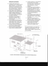
DRAIN TRAP ASSEMBLY
Check for proper fit
of
the entire assembly
Before cementing the individual
components together. Place the flexible
pipe coupling on the sub protruding from the
90 degree elbow connected to the
condensate collector, then insert the 6 inch
pipe stub and tighten the clamps on each
end
of
the flexible coupling.
Attach the tee to the stub coming out
of
the
furnace and insert 10 inch stub to bottom
of
the tee. Attach the trap assembly to the
bottom
of
the stub using PVC pipe coupling.
Do
Not
use
pipe
cement
on
the
flexible
pipe
coupling.
Add water to the trap until
some runs out
of
the drain overflow. Do not
install the drain in areas
SUbject
to freezing.
DRAIN CONNECTION
Insert the ~ inch
10
tUbing through the hole
in the cabinet and press on to the barb
fitting.
Do
not
use
excessive
force
on
the
drain
pan. Connect the other end to
the top 90 degree barb on the drain trap
assembly. Connect another piece
of
tubing
to the bottom
of
the tee on the drain trap
and run to the condensate neutralizer. The
condensate neutralizer must lay in a
horizontal position. Connect installer
furnished tUbing (type UVT or equivalent,
~"
10)
to the other end
of
the condensate
neutralizer and run to a drain. Do not install
the drain in areas subject to freezing.
14