


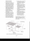
When the furnace is used in connection with
a cooling unit, the furnace should be
installed in parallel with
or
on the upstream
side
of
the cooling unit to avoid
condensation in the heating element. With
a parallel flow arrangement, the dampers or
other means used to control the flow
of
air
must be adequate to prevent chilled air from
entering the furnace and,
if
manually
operated, must be equipped with means to
prevent operation
of
either unit unless the
damper is in the full heat or cool position.
FILTERS - READ THIS SECTION BEFORE
INSTALLING THE RETURN AIR
DUCTWORK
A FILTER MUST BE USED WITH THIS
FURNACE. Discuss filter maintenance with
the building owner. Filters are shipped with
this furnace. Filters must comply with UL900
or CAN/ULCS111 standards.
If
the furnace
is
installed without filters. the
warranty will be voided.
Inspect Filter Frequently!
Replace 3 times each heating season.
XI. START-UP PROCEDURE &
ADJUSTMENT
Please read the procedures outlined below
and familiarize yourself with the appliance
sequence
of
operation before conducting
any tests or starting the appliance.
Note: A separate start-up form is attached
to the installation instructions and must be
completed and returned to the
manufacturer for warranty registration
within 30 days
of
installation.
Check that furnace is installed level. This is
important since the secondary heat
exchanger is pitched at 3 degrees for proper
condensate drainage. Check with a
carpenters level and shim accordingly.
Verify that the fuel supply lines are leak-
free. Inspect all connections for air leaks.
Fuel system integrity is often assumed, but
cannot be overlooked.
Test
the fuel system
for integrity. Even a small leak can cause a
multitude
of
burner issues. Never use
compression fittings.
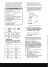
Verify pump pressure with appropriate test
instrument. (140 PSI) for Adams
INTERburner Mark 10 or Beckett
NX.
Check pump seal by shutting
off
pump and
noting the pressure drop. The pump
pressure should drop approximately 20%
and hold indefinitely.
Prime oil filter supplied with the appliance
before bleeding air from system. Purge the
oil pump
of
air
in the system as soon as the
burner motor starts rotating by opening
bleeder valve on pump and catch oil in
suitable container.
Check post-purge timing on primary safety
control by examining dip-switch
configuration on the primary control. This
control is factory set
at
8 minutes post purge
time.
Locate fan control in blower compartment.
Check
blower-on time delay. Set delay for
30 seconds.
Verify blower-off delay setting
at
390-600
seconds. This is required for proper heat
removal from the heat exchanger once the
thermostat is satisfied.
Do
not
remove blower deck support bracket
located in the blower compartment. This
bracket may be confused for a shipping
bracket and must
not
be removed. This
bracket is installed in up-flow and counter-
flow models only.
It is a sheet metal
support bracket in the blower compartment.
Prime condensate drain trap with water.
Operate the burner for (3) minutes on, (3)
minutes
off
twice. Operate the burner for
approximately 30-40 minutes to
cure
the
internal ceramic fiber combustion
chamber.
Be aware
of
moderate
odor/smoke upon initial firing and gradually
diminishing to normal over the break-in
period. Note the air handler should be
operating
at
all times during the break-in
period and final tuning.
You are now ready for the final fine-tuning.
The
burner
air
settings are approximate
and needs to be adjusted
to
the vent system
in the field for most efficient operation.
17