


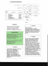
STANDARD FURNACE CONNECTIONS
It is the responsibility
of
the installer to
ensure that the piping connections to the
furnace are secure, airtight, and adequately
supported.
All furnaces are shipped with a combustion
air connection on the cabinet exterior and a
flue connector on the inside
of
the cabinet
on the condensate collector box.
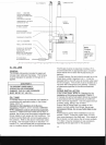
VENTIFLUE PIPE
VenUflue pipe can be secured to the
vent/flue coupling using the rubber coupling
and worm gear hose clamps provided with
this furnace (see "Standard connections"
figure). The rubber coupling allows
separation
of
the vent/flue pipe from the
furnace dUring servicing.
Combustion
Air
and Vent piping should be
routed in a manner to avoid contact with
refrigerant lines, metering devices,
condensate drain lines, etc. If necessary,
clearances may be increased by utilizing two
45 degree Long-Sweep Elbows and creating
an "S" joint to provide additional space at
connection locations. This joint can be
rotated on the fitting to establish maximum
clearance between refrigerant lines,
metering devices, and condensate drain
lines, etc. This joint is the equivalent
of
one
90 degree elbow when considering elbow
count.
NOTE: Do not use other commercially
available "no hub connectors" due to
possible material conflicts. The venUflue
pipe can also
be secured using a PVC or
ASS elbow
or
coupling using the appropriate
glue (see Section VI, Materials and Joining
Methods).
VENTIFLUE AND COMBUSTION
AIR
PIPE
LENGTHS
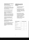
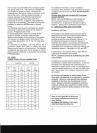
Refer to the following table for applicable
length, elbows, and pipe diameter for
construction
of
the venUflue and combustion
air
intake pipe systems
of
a direct vent (dual
pipe) installation. The number
of
elbows
tabulated represents the number
of
elbows
and/or tees in each (Vent/Flue
&
Combustion
Air
Intake) pipe. Elbows and/or
tees used in the terminations must
be
included when determining the number
of
elbows in the piping systems.
If the combustion air intake pipe is to be
installed above a finished ceiling or other
area where dripping
of
condensate will be
objectionable, insulation
of
the combustion
air pipe may be reqUired. Use W thick
closed cell foam insulation such as Armaflex
or Insultube where reqUired.
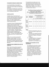
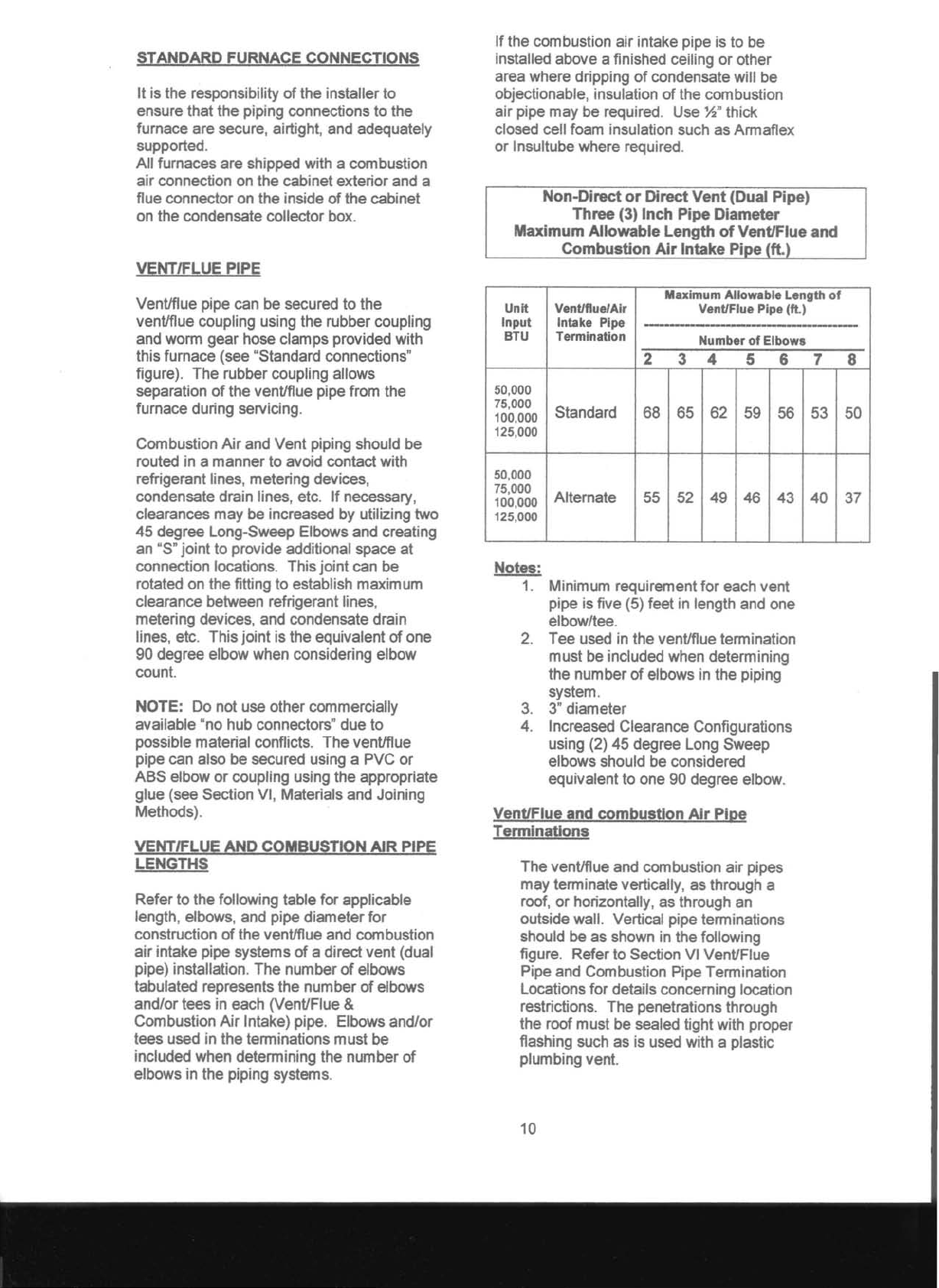
Non-Direct
or
Direct
Vent
(Dual Pipe)
Three
(3)
Inch
Pipe
Diameter
Maximum
Allowable
Length
of
Vent/Flue
and
Combustion
Air
Intake
PiDe
(ft.)
Unit
Input
BTU
Vent/flue/Air
Intake Pipe
Termination
Maximum Allowable Length
of
Vent/Flue Pipe
(ft.)
-------------------
Number
of
Elbows
2
3
4
5 6 7
8
50,000
75,000
100,000
125,000
Standard
68
65 62 59 56 53 50
50,000
75,000
100,000
125,000
Alternate
55
52
49 46
43 40 37
Notes:
1.
Minimum reqUirement for each vent
pipe is five (5) feet in length and one
elbow/tee.
2.
Tee used in the vent/flue termination
must be included when determining
the number
of
elbows in the piping
system.
3.
3"
diameter
4.
Increased Clearance Configurations
using (2) 45 degree Long Sweep
elbows should be considered
equivalent to one 90 degree elbow.
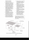
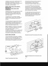
Vent/Flue
and
combustion
Air
Pipe
Tenninations
The vent/flue and combustion air pipes
may terminate vertically, as through a
roof, or horizontally, as through an
outside wall. Vertical pipe terminations
should be as shown in the following
figure. Refer to Section VI Vent/Flue
Pipe and Combustion Pipe Termination
Locations for details concerning location
restrictions. The penetrations through
the roof must be sealed tight with proper
flaShing such as is used with a plastic
plumbing vent.
10