


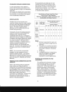
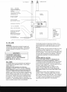
The furnace may be installed with a one-pipe system
with gravity feed
or
lift. The maximum allowable lift
on a single line system is 8 feet. Lift should be
measured from the bottom (outlet)
of
the tank,
to
the
inlet
of
the burner. Sizing a single line system is
complex because
of
the difficulty estimating the
pressure drop through each fitting, bend and
component in the line. In general, keep single line
systems short as possible. Two-stage oil pumps are
available for either the INTERburner or Beckett
burner.
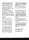
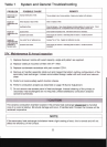
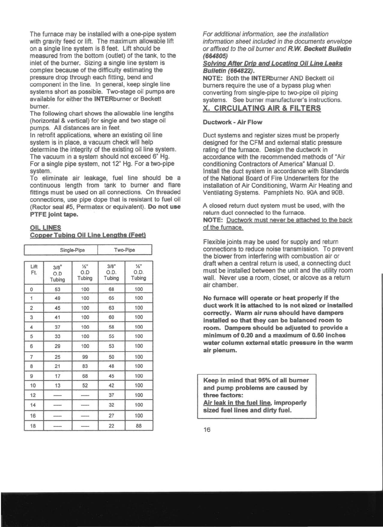
The following chart shows the allowable line lengths
(horizontal & vertical) for single and two stage oil
pumps. All distances are in feet.
In retrofit applications, where an existing oil line
system is in place, a vacuum check will help
determine the integrity
of
the eXisting oil line system.
The vacuum in a system should not exceed 6" Hg.
For a single pipe system, not 12" Hg. For a two-pipe
system.
To
eliminate air leakage, fuel line should be a
continuous length from tank to burner and flare
fittings must
be
used on all connections. On threaded
connections, use pipe dope that is resistant to fuel oil
(Rector seal #5, Permatex or eqUivalent). Do
not
use
PTFE
joint
tape.
OIL
LINES
Copper
Tubing
Oil
Line
Lengths
(Feet)
Single-Pipe
Two-Pipe
Lift
Ft.
3/8"
0.0
Tubing
Yo"
0.0
Tubing
3/8"
0.0.
Tubing
Yo"
0.0.
Tubing
0
53
100
68
100
1
49
100
65
100
2
45
100
63
100
3
41
100
60
100
4
37
100
58
100
5
33
100
55
100
6
29
100
53
100
7
25
99
50
100
8
21
83
48
100
9 17 68
45
100
10
13
52
42
100
12
- -
37
100
14
- -
32
100
16
- -
27
100
18
--
-
22
88
For additional information,
see
the
installation
information sheet included
in
the documents envelope
or affixed
to
the
oil burner and
R.
W.
Beckett
Bulletin
(664805)
SoMng
After
Drip
and
Locating
Oil
Line
Leaks
Bulletin (664822).
NOTE: Both the INTERburner AND Beckett oil
burners require the use
of
a bypass plug when
converting from single-pipe to two-pipe oil piping
systems. See burner manufacturer's instructions.
X.
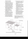
CIRCULATING AIR & FILTERS
Ductwork·
Air
Flow
Duct systems and register sizes must be properly
designed for the CFM and external static pressure
rating
of
the furnace. Design the ductwork in
accordance with the recommended methods
of
"Air
conditioning Contractors
of
America" Manual
D.
Install the duct system in accordance with Standards
of
the National Board
of
Fire Underwriters
for
the
installation
of
Air
Conditioning, Warm
Air
Heating and
Ventilating Systems. Pamphlets
No.
90A and 90B.
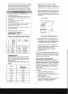
A closed return duct system must be used, with the
return duct connected to the furnace.
NOTE: Ductwork must never
be
attached to the back
of
the furnace.
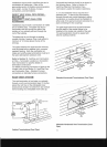
Flexible joints may be used for supply and return
connections to reduce noise transmission.
To
prevent
the blower from interfering with combustion air
or
draft when a central return is used, a connecting duct
must be installed between the unit and the utility room
wall. Never use a room, closet, or alcove as a return
air chamber.
No
furnace
will
operate
or
heat
properly
if
the
duct
work
it
is
attached
to
is
not
sized
or
installed
correctly.
Warm
air
runs
should
have
dampers
installed
so
that
they
can
be
balanced
room
to
room.
Dampers
should
be
adjusted
to
provide
a
minimum
of
0.20
and
a
maximum
of
0.50
inches
water
column
external
static
pressure
in
the
warm
air
plenum.
Keep
in
mind
that
95%
of
all
burner
and
pump
problems
are
caused
by
three
factors:
Air
leak
in
the
fuel
line,
Improperly
sized
fuel
lines
and
dirty
fuel.
16