


10 11
GD-6
Main Fan Power
120VAC
ALARM
120VAC
Power
Exhaust Fans
coil
coil
power output
GD-6
– +
power output
– +
8 7 6 5 4
4
3
3
2
2
1
1
1 13 3 4 5 6 7 8 92
24 V RET
N.C.
N.C.
N.C.
N.O.
N.O.
N.O.
COM
COM
COM
-1 LOOP
+1 LOOP
+24 VDC
-1 LOOP
+1 LOOP
+24 VDC
- Strobe
+ Strobe
- Horn
+ Horn
Relay 1
Gnd
Panel Power
120/250VAC
3M™ MACURCO™
DETECTION AND VENTILATION
CONTROL PANEL DVP-120
STARTER RELAYS
120VAC COILS
Relay 2 Relay 3
24 V RET
LN
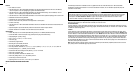
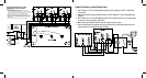
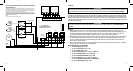
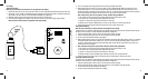
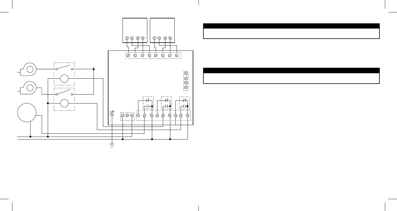
Typical Connection to the 3M™ Macurco™ Detection and Ventilation
Control Panel DVP-120
Gas detection and exhaust fan control is provided by a 3M™ Macurco™ DVP-120 system. This System
will use the GD-6 Combustible Gas to current transducer, Nitrogen Dioxide to current transducers or
Carbon Monoxide to current transducers. Each transducer will measure the level of the target gas and
provide this information to the DVP-120 over a 4-to-20mA current loop.
All power and signal connections for the transducers are provided from the DVP-120 control panel, via
unshielded four conductor cable. The DVP-120 control panel provides three relays which can be used for
ventilation fan control or alarm signaling. These relays (SPDT-Form C) are for pilot duty only, capable of
switching 10 amps loads up to 240VAC.
NOTE:
1. Power connections at the sensor are non-polarized.
Power Up
W WARNING
W WARNING
Each time the unit is turned on it performs a self-test, which activates visual alarms. If the self-test fails, or if all the alarms
do not activate, do not use. Failure to do so may adversely affect product performance and result in sickness or death.
The 3M™ Macurco™ GD-6 Combustible Gas Detector cycles through an internal self-test cycle for the first minute that it is
powered. The unit will execute the test cycle any time power is dropped and reapplied (i.e. power failure). During the self-test
cycle the unit will display the firmware version number, then count down from 60 to 0 and finally go into normal operation. The
fan and alarm relay will be activated for the power-up cycle unless the “Power Up Test” (PUt) option is OFF. The indicator light
(LED) will flash green during the self-test cycle. At the end of the 1 minute cycle, the unit will take its first sample of the air and
the light will turn solid green.
Do not cover or obstruct visual alarm LED. Doing so may adversely affect product performance and result in sickness
or death.
Operation
1. With the display function turned “On”, the 3M™ Macurco™ GD-6 Combustible Gas Detector will show the current
concentration of gas % LEL or “0” (zero) in clean air. When the gas concentration reaches the Fan Relay setting (10% LEL,
for example) the display will flash back and forth between “FAn” and “10”. With the display function turned ”Off”, the
display does not show the gas concentration, but will show “FAn” as long as the fan relay is activated.
2. With the display function turned “On” and the gas concentration reaching the alarm relay setting, (20% LEL, for example)
the display will flash back and forth between “ALr” and “20”. The buzzer will sound indicating “Alarm” if the buzzer is
turned “On”. With the display function turned off the display does not show the gas concentration, but will show “ALr”
when the Alarm relay is activated.
3. With the 4-20mA function turned “On”, the 4-20mA output will correspond to the concentration (0-50% LEL). The display
will show “FAn” and “ALr” and sound as outlined above.
Default Configuration – Factory Settings
• ThedefaultDisplay setting is Off
• ThedefaultPower Up Test setting is On
• ThedefaultBuzzer setting is Off
• ThedefaultAlarm Relay setting is activation at 20% LEL
• ThedefaultFan Relay Delay setting is 3 minutes
• ThedefaultFan Minimum Runtime setting is OFF
• ThedefaultFan Relay setting is activation at 10% LEL
• ThedefaultAlarm Relay Configuration is Normally Open
• Thedefault4-20mA Output setting is OFF