


18 19
Gas Testing
Testing the Fan Relay
Note: The gas concentration to activate the fan relay depends on the setting.
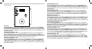
1. Remove the Philips screw on the front of the 3M™ Macurco™ GD-6 Combustible Gas Detector. Remove the front cover.
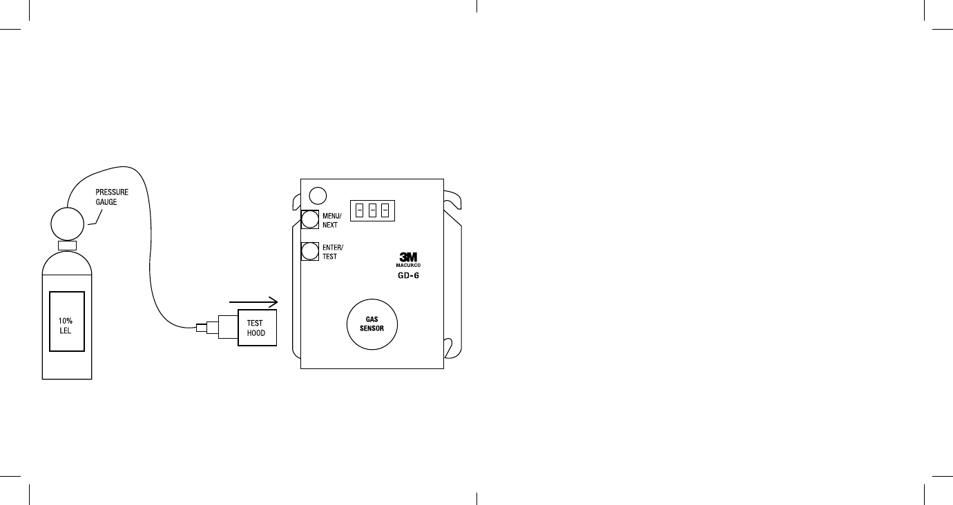
2. Connect the 10% LEL cylinder of Combustible Gas to the regulator. Ensure that the gas used for calibration matches the
gas selected in the 3M™ Macurco™ GD-6 Combustible Gas Detector configuration.
3. Assemble regulator, hose and test hood and place the test hood over the gas sensor.
4. Check the pressure gauge on the regulator. If you have 25psi or less you will need to replace the gas canister.
Note: The time to activate the fan relay depends on the delay setting.
5. Turn on the regulator to start the gas flow and wait with the gas applied continuously.
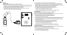
6. With the display function turned “On”, the 3M™ Macurco™ GD-6 Combustible Gas Detector will show the current
concentration of gas or “0” (zero) in clean air. When the gas concentration reaches the fan relay setting (5% LEL, for
example) the display will flash back and forth between “FAn” and “5”. With the display function turned ”Off”, the display
does not show the gas concentration, but will show “FAn” as long as the fan relay is activated
Note: If the Fan relay does not close within 2 minutes, consider these possibilities:
a. Gas cylinder is empty, check the pressure gauge. Replace the gas cylinder if 25psi or less.
b. Unit needs to be re-calibrated (go through recalibration and re-test).
c. Detector is in need of servicing (return unit to factory for servicing).
d. Detector has fan relay set to disable (OFF) or 20% LEL. Set fan relay to 5% LEL and repeat the test.
7. Remove the gas from the sensor. Proceed to test the alarm relay or replace the top cover.
Testing the Alarm Relay
Note: The gas concentration to activate the Alarm relay depends on the setting.
Connect the 20% LEL cylinder of Combustible Gas to the regulator. Ensure that the gas used for calibration matches the gas
selected in the 3M™ Macurco™ GD-6 Combustible Gas Detector configuration.
1. Check the pressure gauge. If there is 25psi or less the cylinder should be replaced.
2. Place the test hood over the gas sensor. Turn on the regulator to start the gas flow.
3. The Fan relay should activate according to the settings.
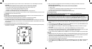
4. With the display function turned “On” and the gas concentration reaching the Alarm Relay setting, (20% LEL, for example)
the display will flash back and forth between “ALr” and “20”. The buzzer will sound indicating “Alarm” if the buzzer is
turned “On”. With the display function turned off the display does not show the gas concentration, but will show “ALr”
when the Alarm relay is activated.
5. Note: If the Alarm relay fails to operate within 2 minutes, consider these possibilities:
a. Gas cylinder is empty, check the pressure gauge. Replace the gas cylinder if 25psi or less.
b. Unit needs to be re-calibrated (go through recalibration and re-test).
c. Detector is in need of servicing (return unit to factory for servicing).
d. Detector has Alarm relay set to disable (OFF). Set Alarm relay to 20% LEL and repeat the test.
6. Remove the gas from the sensor after test. Proceed to test the 4-20mA output or replace the top cover.
Testing the 4-20mA current loop
Connect the 20% LEL cylinder of Combustible Gas to the regulator. Ensure that the gas used for calibration matches the gas
selected in the 3M™ Macurco™ GD-6 Combustible Gas Detector configuration.
1. Check the pressure gauge. If there is 25psi or less the cylinder should be replaced.
2. Place the test hood from the regulator over the gas sensor. Turn on the regulator to start the gas flow.
3. The fan relay should activate according to the settings.
4. The alarm relay should activate according to the settings.