


6 7
Installation
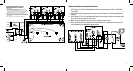
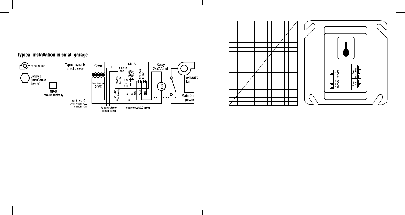
1. The 3M™ Macurco™ GD-6 Combustible Gas Detector mounts on a type 4S electrical box supplied by the contractor.
2. Connect the 3M™ Macurco™ GD-6 Combustible Gas Detector to Class 2 power supply only. It is suggested to use a
separate transformer for powering the unit or units because of possible interference’s from other devices on the same
power supply.
3. Connect the 3M™ Macurco™ GD-6 Combustible Gas Detector to the control cables with terminal plugs. When making
connections, make sure the power is off.
4. TherearetwoterminalsforPower:12to24VACor12to48VDC,withnopolaritypreference.
5. There are two terminals for the dry alarm relay contacts, again with no polarity preference. The alarm relay can switch up
to 0.5A, 200V, or 10VA. The alarm relay is activated if gas reaches or exceeds the alarm settings.
6. The alarm relay can be configured to normally open (default) (N.O.) or normally closed (N.C.) and will activate if the gas
concentration exceeds alarm set point (5, 10, 15, 20 (default), 25% LEL). It will deactivate once the gas concentration drops
below the alarm set point. Note that the “disable” setting will cause the alarm relay not to engage at all.
7. The dry contact, SPDT fan relay has three terminals. The common (COM.), normally open (N.O.) and the normally closed
(N.C.) contact. The fan relay can switch up to 5.0A up to 240VAC. (see OPERATION section of these User Instructions for
details on relay settings).
8. The fan relay can be wired to normally open (N.O.) or normally closed (N.C.) and will engage if the fan setting (1, 2, 3,
4, 5, 6, 7, 8, 9, 10 (default), 11, 12, 13, 14, 15, 16, 17, 18, 19, 20% LEL) is exceeded for the fan relay delay time (0, 1,
3(default),5,10minutes).Thefanrelaywilldisengageoncebothoftheseconditionshavebeenmet:1.Combustible
gas concentration has dropped below fan setting and 2. Fan relay run time (0 (default), 3, 5, 10, 15 minutes) has been
exceeded. Note that the “disable” fan setting will cause the fan relay to not engage. The fan relay will engage in trouble
fault condition and will disengage once trouble fault condition is cleared.
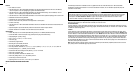
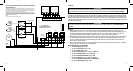
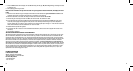
9. The Current Loop is 4mA in clean air and 4-20mA for 0-50% LEL.
Percent % LEL
0
12.5
25
37.5
50
4
Output in mA: GD-6
9 14 20
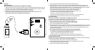
GD-6 rear view with
Modular Connectors