


29
Special Set-Up Procedure (Continued)
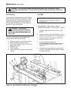
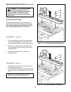
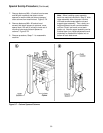
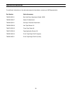
4. Remove M6 x 16 hex hd screw, special washer
and drive belt width adjustment crank.
Figure 5-5.
5. Remove side covers (2) from each side of
machine bed. Figure 5-5.
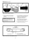
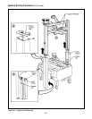
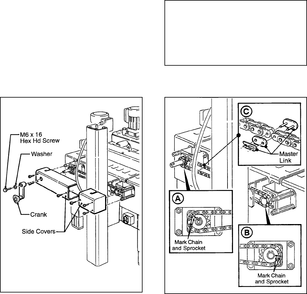
6. Remove chain. If necessary, slip width
adjustment crank on shaft and rotate until chain
master link is in convenient position for removal.
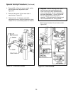
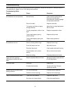
Important – Before removing chain, mark
both front and rear sprockets/chain with
chalk or paint to be sure sprockets/chain
when re-assembled, will be in same position
as before disassembly. Figure 5-6A and B.
Do not rotate sprockets once chain is
removed. (This would result in the right and
left drive assemblies not being parallel.)
Remove chain master link and remove chain.
Figure 5-6C.
Figure 5-6 – Chain Removal
Figure 5-5 – Crank/Chain Guards