12 Visitor and Community Network Access Concentrator Installation Guide
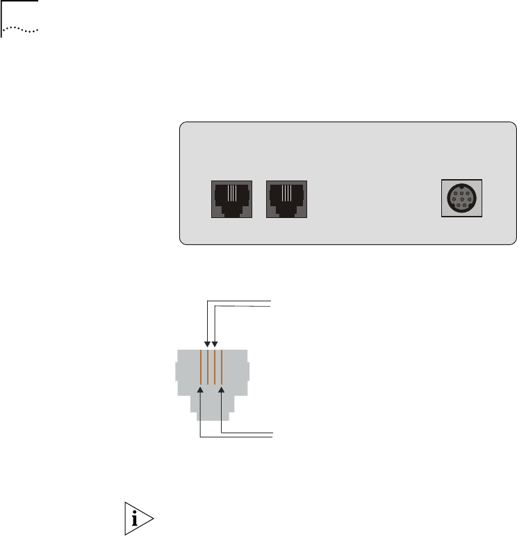
■ The outer wire pair carries only voice.
Figure 4 VCN Access Point Rear Panel
Figure 5 The Four Wires of the Telephone Cable
2
Disconnect the punch-down Krone connector for the inner wire pair from
the PBX punch-down block.
The outer wire pair remains connected to the PBX punch-down block
since it will not carry data.
3
Connect the Krone connector of the inner wire pair to the new VCN AP
punch-down block, which has been added.
4
Connect another punch-down Krone connector from the VCN AP
punch-down block to the back of the patch panel.
5
Connect an additional punch-down Krone connector from the patch
panel to the PBX punch-down block to carry voice transmissions of the
inner wire pair to the PBX.
6
Repeat step 1 through step 5 for up to 24 telephone lines.
Figure 6 shows the resulting infrastructure.
PHONE
LINE
DC-IN
Inner wire pair
Outer wire pair


