Publication 1771-6.5.132 - June 2000
2-8 Planning Your Configuration and Data Mapping Your Devices
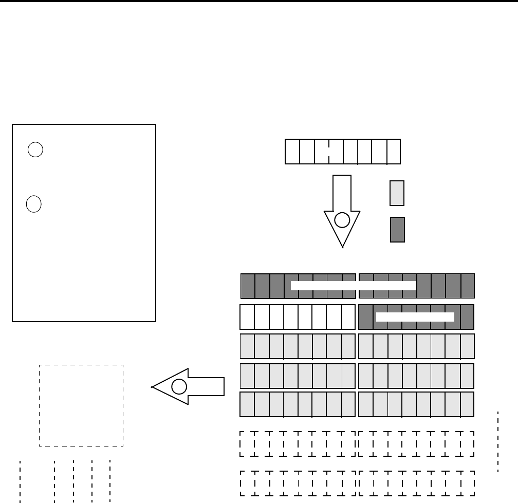
Mapping Photoeye Input Data for a Block Transfer Read
The photoeye’s input byte is mapped to the scanner’s block transfer
read data table through a 62 word BTR. In this example, we use data
file N9.
What’s Happening?
Important: The 1771-SDN module only
makes the data available for the
processor to read. The 1771-SDN
module does not move the data to the
processor.
= unused bits
1
Photoeye Input Byte
1 byte
1
2
The status and data bits from
the photoeye are mapped into
the 1771-SDN Scanner’s BTR
data table.
The BTR data table is then
transferred via a BTR to the
PLC-5 processor’s input data
file.
S D
2
1
This mapping is based upon the example in chapter 4.
The actual mapping for your system may be different.
Note: This example uses
1-slot addressing.
Word 0
Word 1
Word 2
Word 3
Word 4
Word 61
1771-SDN Scanner Block Transfer Read Data Table
S D
= bits reserved for module
status word
N9:0 0000 0000 0000 0000
N9:1 0000 00SD 0000 0000
N9:2 0000 0000 0000 0000
N9:3 0000 0000 0000 0000
N9:5 0000 0000 0000 0000
N9:4 0000 0000 0000 0000
PLC-5 Processor
Input Data File
1
N9:61 0000 0000 0000 0000
Example: The Status bit from the photoeye appears in the PLC-5
processor’s integer file at address N9:1/9.
The Data bit from the photoeye appears in the PLC-5 processor’s
integer file at address N9:1/8.
reserved for module status word
RediSTATION


