Publication 1771-6.5.132 - June 2000
D-4 Data Map Example
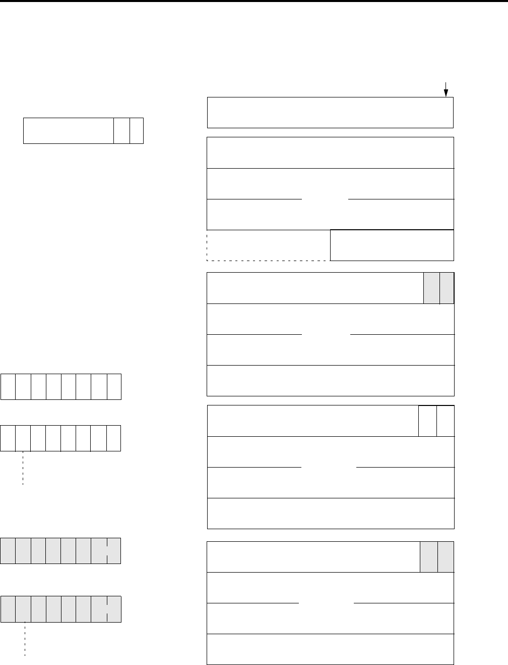
In 1-slot addressing mode eight bits are available for discrete input
mapping, as shown below.
node #1 1 byte
S D
node #2 1 byte
S D
node #1 1 byte
S D
node #2 1 byte
S D
Channel A
Channel B
to node #62
to node #62
Module Status
39 38 37 36 35 34 33 32 31 30 29 28 27 26 25 24
15 0
79
95
143
159
206
222
270
81 80
2D 1D
145 144
2S 1S
208 207
2S 1S
Input Data Bits from Channel A Devices
bits 24-79
bits 80-143
Input Data Bits from Channel B Devices
bits 144-206
Status Bits from Channel A Devices
Status Bits from Channel B Devices
bits 207-270
word 0
word 1
word 2
word 3
word 4
word 5
word 6
word 7
word 8
word 9
word 10
word 11
word 12
word 13
word 14
word 15
word 16
Bit numbering in the data table is right
to left, beginning with zero.
In 1-slot addressing, the first eight bits
after the module status word are used for
the input image table. This table is for
discrete input bits. Data bits for node
addresses 1-8 are mapped to this area in
ascending numeric order according to
node address.
Device Input
208 207
2S 1S
ote: 1 wor
= 2
ytes
1 byte = 8 bits
Input Image Table
23 22 21 20 19 18 17 16
2D 1D
(for discrete input data bits)
Note:
D = data bit
S = status bit
1D & 1S = data and
status bits for node #1
2D & 2S = data and
status bits for node #2


