Publication 1771-6.5.132 - June 2000
Data Map Example D-7
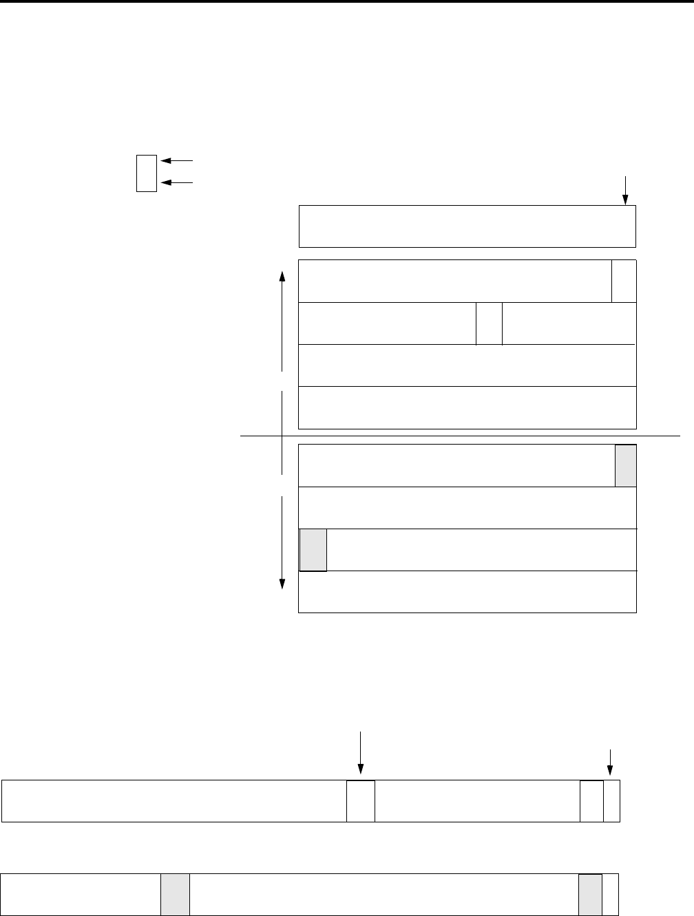
Output Data Table Formats
The following illustrates an output data mapping scheme example for
a scanner in 2-slot addressing mode.
Module Status
31
15 0
79
95
125
N45
143
80
N1
word 0
word 1
word 2
word 3
word 4
word 5
word 6
word 7
word 8
In 2-slot addressing mode, the output bits
for channel A and channel B devices are
written to the scanner’s output data table.
The bits are stored in ascending numeric
order, according to node address. The
mapping begins with channel A devices at
bit 16 of the table.
There are 64 possible node addresses per
network. Channel A devices fill the first
four words (after the module status word).
Channel B devices fill the last four words
of the table.
Note: 1 word = 2 bytes
1 byte = 8 bits
16
N1
bit number
node number
N1 = node #1
16
N1
Output Data Strobe Message channel A
Output Data Strobe Message channel B
63 - - - - - - - - - - - - - - - - - - - - - - - - - 23 - - - - - - - - - - - - - - - 1 0
N23
N1
63 - - - - - - - - - - - 45 - - - - - - - - - - - - - - - - - - - - - - - - - - - - - 1 0
N45
N1
Bit numbering in the data table is
right to left, beginning with zero.
Each node’s output bit is mapped to a bit number in the
strobe message that directly corresponds to that
particular node’s MAC ID. For example, the output bit
for node #23 is mapped to strobe bit #23.
Bit numbering in the data table is
right to left, beginning with zero.
Channel B
Channel A
The scanner takes the output bits from its
output data table and organizes them into a
strobe message. The strobe message
contains one bit for each node address,
0-63. In default mode, the scanner is node
63; therefore, this bit is empty. The scanner
sends a separate strobe message to each
network, via channel A and channel B.
39
N23


