NOTE: DIAGRAMS & ILLUSTRATIONS ARE NOT TO SCALE.
21
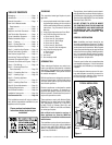
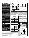
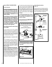
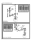
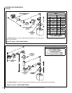
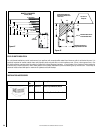
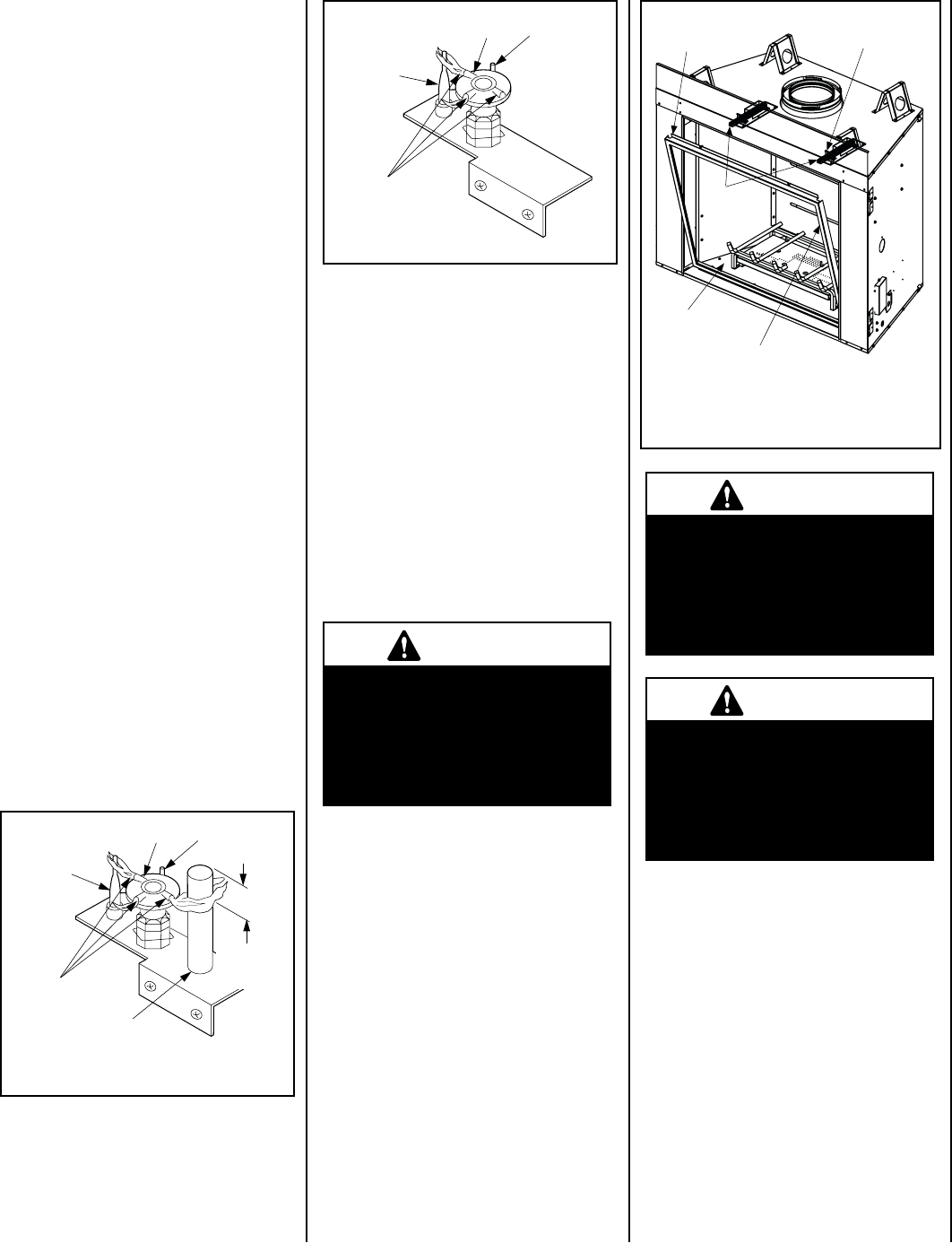
Figure 35
ELECTRONIC
Flame
Sensor
Hood
Ignitor Rod
Pilot
Nozzels
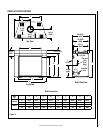
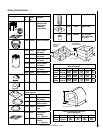
Glass Door Latch (2)
Glass Door Assembly
Firebox Floor
Top Flange Glass Door
Frame Assembly
Screws
WARNING
Handle this glass with extreme
care! The glass panel is sus-
ceptible to damage — do not
scratch while handling or while
re-installing the glass door
frame.
WARNING
When reinstalling the glass door,
the door latch screws must be
securely tightened to prevent
the glass door from falling out,
which could potentially cause
damage and possible injury.
WARNING
Do not operate appliance with
the glass front removed, cracked
or broken. Replacement of
the glass should be done by a
licensed or qualified service
technician.
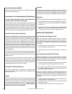
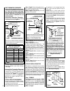
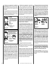
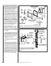
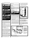
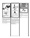
Figure 37 -
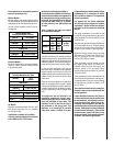
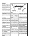
Figure 36
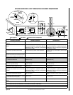
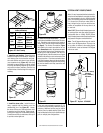
INSTALLING THE GLASS DOOR
MILLIVOLT
Thermocouple
Hood
Igniter Rod
3/8" Min
(9 mm)
Thermopile
Pilot
Nozzels
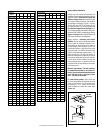
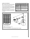
Step 10. BURNER ADJUSTMENTS
Flame Appearance and sooting
Proper flame appearance is a matter of taste.
Generally, most people prefer the warm glow of
a yellow to orange flame. Appliances operated
with air shutter openings that are too large will
exhibit flames that are blue and transparent.
These weak, blue and transparent flames are
termed anemic.
Step 8. CHECKING APPLIANCE OPERA-
TION
With gas line installed run initial system check-
out before closing up the front of the unit. Follow
the pilot lighting instructions provided For
piezo igniter location refer to Figure 34 (millivolt
appliances only).
Note: Lighting Instructions are also found on
the literature tag tied to the bracket above the
gas valve. To access the tag, reach into the
right side opening.
When first lighting the appliance, it will take
a few minutes for the line to purge itself of
air. Once purging is complete, the pilot and
burner will light and operate as indicated in
the instruction manual. Subsequent lighting
of the appliance will not require such purging.
Inspect the pilot flame (remove logs, if neces-
sary, handling carefully).
Millivolt Appliance Checkout
The pilot flame should be steady, not lifting
or floating. Flame should be blue in color with
traces of orange at the outer edge.
The top 3/8" (10 mm) at the pilot generator
(thermopile) and the top 1/8" minimum (tip)
of the quick drop out thermocouple should be
engulfed in the pilot flame.
The flame should project 1" (25 mm) beyond the
hood at all three ports (see Figure 35). Replace
logs if removed for pilot inspection.
To light the burner; rotate the gas valve control
knob counterclockwise to the “ON” position
(“ON” will be at the bottom side of the valve)
and turn “ON” the appliance mounted ON/OFF
switch.
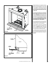
Install the door modesty shield on top flange
glass door as follows: grab the door modesty
shield with both hands, with the open hem
going down and engage it with the upper lip
of the glass door frame by pushing it all the
way down. Make sure the installed shield is
firmly in place.
With the firescreen hanging on the screen rod,
insert the right side of the rod into the existing
hole on the right modesty panel. Bend down
the rod at the center and drop the left end into
the slot on the left modesty panel, being careful
not to scratch the paint.
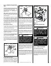
Step 9. INSTALLING THE GLASS DOOR
Retrieve the glass door. Visually inspect the
gasket on the backside of the frame. Gasket
surface must be clean, free of irregularities
and seated firmly.
Position the door in front of the firebox opening
with the top of the door held away from the
fireplace (Figure 37). Lower the bottom of the
door assembly on the bottom door track and
set on padded surface. Pivot the door up after
engaging and centering in the base channel.
Using a Phillips screwdriver, fasten the door
frame to the door latch with the two (2) screws.
The latch should pull forward to engage the
door frame.
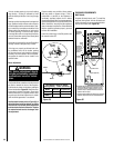
Electronic Appliance Checkout
To light the burner, turn ‘ON’ the optional remote
wall switch or turn the appliance mounted ON/
OFF switch to the “ON” position. Ensure the
igniter lights the pilot. The pilot flame should
engulf the flame rod as shown in Figure 36.