19
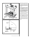
CAUTION
Ground supply lead must be connected to the wire attached to the green
ground screw located on the outlet box. See Figures 32A and 32B. Failure
to do so will result in a potential safety hazard. The appliance must be
electrically grounded in accordance with local codes or, in the absence of
local codes, the National Electrical Code, ANSI/NFPA 70-latest edition. (In
Canada, the current CSA C22-1 Canadian Electrical Code).
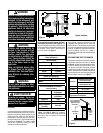
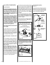
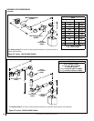
Step 4. FIELD WIRING
Caution: Label all wires prior to disconnection
when servicing controls. Wiring errors can
cause improper and dangerous operation.
Verify proper operation after servicing.
Refer to Section A for millivolt appliances and
Section B for electronic appliances. The gas
valve is set in place and pre-wired at the factory
on both models.
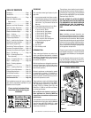
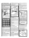
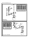
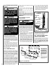
A. Millivolt Wiring (See Figure 31) –
1. Appliance-mounted ON/OFF burner control
switch (rocker switch) is factory installed.
Optional wall-mounted switch, or one of
the optional remote control kits may also
be used.
2. If wall-mounted ON/OFF control is selected
mount it in a convenient location on a wall
near the fireplace.
3. Wire the control switch within the millivolt
control circuit using the 15 feet of 2 conduc-
tor wire supplied with the unit.
Note:
The supplied 15 feet of 2 conductor
wire has one end of each conductor con-
nected to the gas valve circuit and the other
end of each conductor placed on top of the
unit.
Caution: Do Not connect the optional wall
switch to a 120V power supply.
4.
If an optional control switch is installed,
turn the appliance-mounted ON/OFF burner
control switch to the OFF position.
Figure 31
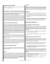
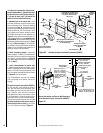
Figure 32A
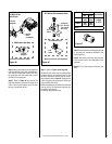
3. Remove the cover plate's knockout and then
feed the power supply wire through the knock-
out opening and into the unit junction box.
4. Connect the black power supply wire to the
power outlet's red pigtail lead and the white
power supply wire to the common terminal of
the outlet as shown in Figures 32A and 32B.
5. Connect the ground supply wire to the pig-
tail lead attached to outlet's green ground
screw.
6. Appliance-mounted ON/OFF burner control
switch (rocker switch) is factory installed.
Optional wall-mounted switch, or one of
the optional remote control kits may also
be used.
7. If wall-mounted ON/OFF control is to be
used, mount it in a convenient location on
a wall near the fireplace.
8. If an optional control is to be used, wire it in
the low voltage circuit (see Figures 32A and
32B).
Note: The supplied 15 feet of 2 conductor wire
has one end of each conductor connected in
parallel with the appliance mounted ON/OFF
burner control switch and the other end of each
conductor placed on top of the unit.
Caution: Do Not connect the optional wall
switch to a 120V power supply.
9. If an optional control switch is installed,
turn the appliance-mounted ON/OFF burner
control switch to the OFF position.
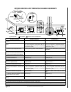
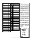
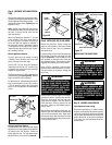
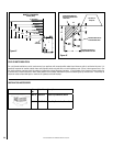
Thermopile
TH
TP
TH
TP
Millivolt Wiring Diagram
If any of the original wire as supplied must be replaced,
it must be replaced with Type AWM 105° C – 18 GA. wire
*OR OPTIONAL WALL-MOUNTED ON/OFF SWITCH OR
OPTIONAL REMOTE CONTROL RECEIVER
*Turn the appliance-mounted ON/OFF burner control switch
to the OFF position if an optional
control switch is installed.
Factory Wired
Field Wired
Schematic Representation Only
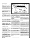
APPLIANCE-MOUNTED ON/OFF SWITCH
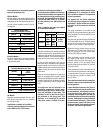
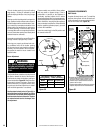
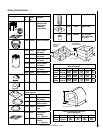
ELECTRONIC
WIRING DIAGRAM
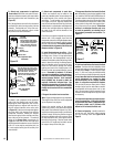
JUNCTION BOX
BLK
W
120 V.
24 V.
TRANSF
ACCESSORY SWITCH
GND
W
BLK
120 VAC
OPTIONAL
ELECTRONIC IGNITION
CONTROL BOARD
*WALL MOUNTED ON/OFF SWITCH (OPTIONAL)
OR REMOTE CONTROL RECEIVER
APPLIANCE MOUNTED
ON/OFF SWITCH
PILOT BURNER
IGNITER-SENSOR
ASSEMBLY
GAS VALVE
EV2
EV1
GROUND
CONNECTOR
GREEN LED
WHITE (6)
WHITE (20)
ORANGE (20)
BLACK (20)
PURPLE (9)
GREEN (12)
BLUE (20)
BLACK (16)
WHITE
W
BLK
GND
FIELD WIRED
FACTORY WIRED
*Turn The Appliance-Mounted ON/OFF Burner Control Switch
To The OFF Position If An Optional Control Switch Is Installed
RED
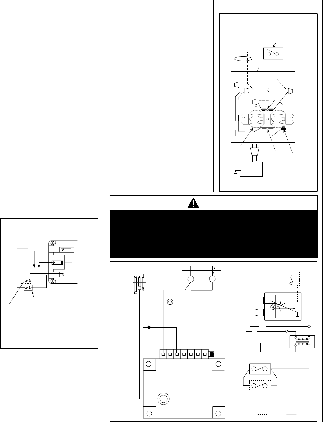
B. Electronic Wiring
(See Figures 32A and 32B)
Note: The electronic appliance must be con-
nected to the main power supply.
1. Route a 3-wire 120Vac 60Hz 1ph power
supply to the appliance junction box.
2. Remove the electrical inlet cover plate from
the side of the unit by removing the plate's
securing screws. See Figure 11 on Page 9.
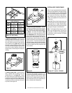
CONTROL CIRCUIT WIRING
120V, 60HZ, 1PH
Factory Wired
Ground
Field Wired
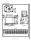
Junction Box
Tab Intact
Tab
Broken
Plug
into this
receptacle
n
e
e
r
G
-
d n
u
o
r
G
* Wall-mounted
ON/ OFF Switch
Fireplace
e
t i
h
W
-
l a r
t
u
e
N
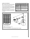
120 VAC - Black
Green
Ground
Screw
White
Green
Neutral
Side of
Receptacle
Hot
Side of
Receptacle
Red
Black
Figure 32B- J-BOX WIRING
10.After the wiring is complete, replace the
cover plate.
See Figure 32B for detailed
drawing of junction box /
receptacle wiring