20
NOTE: DIAGRAMS & ILLUSTRATIONS ARE NOT TO SCALE.
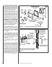
Step 5. REMOVING GLASS DOOR FRAME
ASSEMBLY
Refer to Figure 37 on Page 21 and remove the
front glass door assembly as follows:
To remove the firescreens, lift up the center of
the rod to disengage it from the center bracket,
bend down at center, hold left side with hand
until it disengages from left side, being careful
not to scratch paint. Slowly remove the rod
from the right side.
Using a Phillips screwdriver, unfasten two (2)
screws located at the top of the glass frame.
Tilt the glass frame at the top away from the
unit. Lift it carefully off the bottom door track
and set the door aside, protecting it from
inadvertent damage.
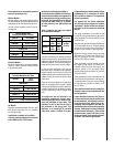
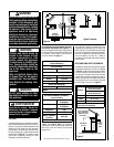
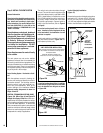
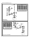
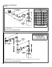
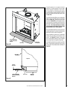
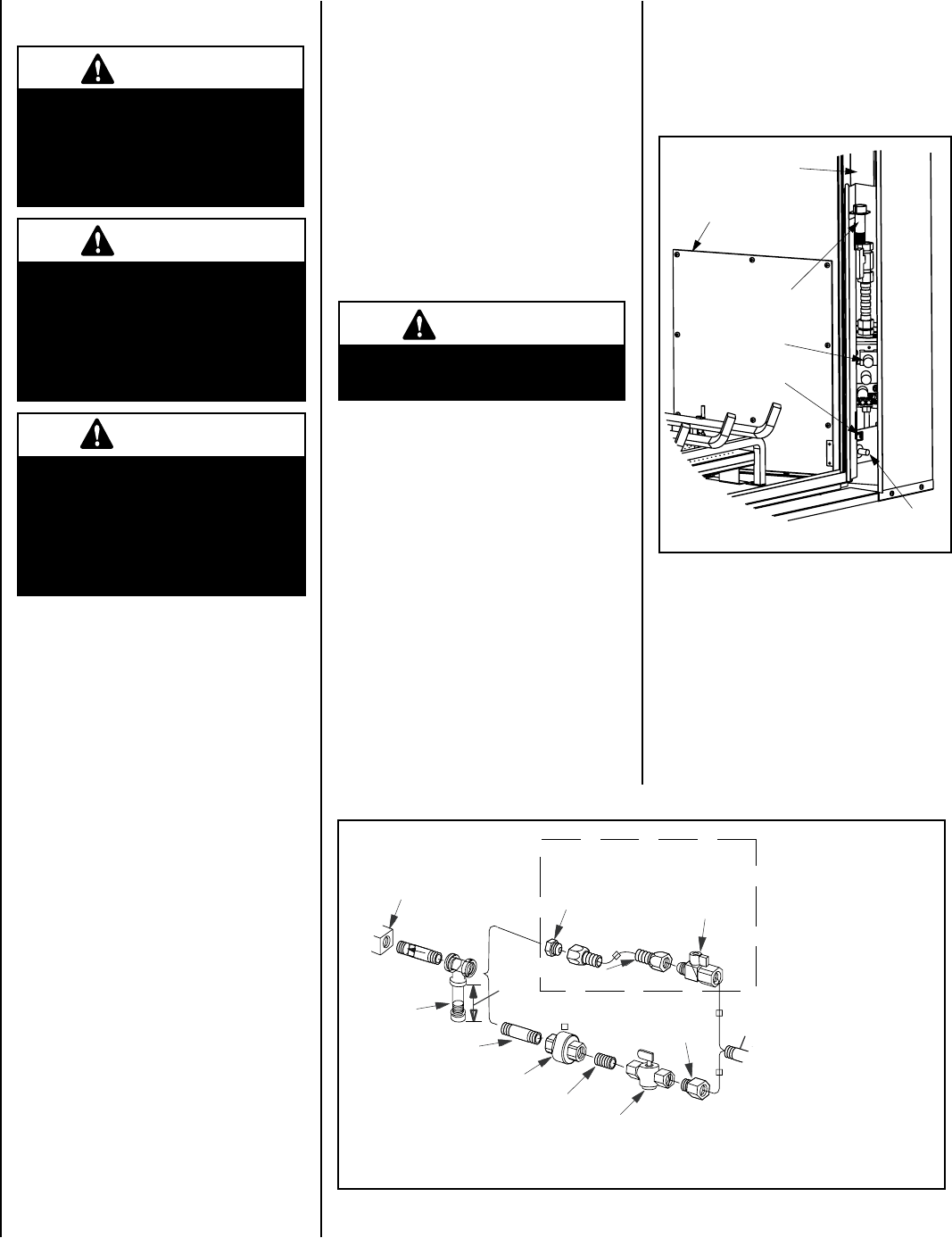
Step 6. CONNECTING GAS LINE
Make gas line connections. Codes require a
shut-off valve mounted in the supply line. Figure
33 illustrates two methods for connecting the
gas supply. The flex-line method is acceptable
in the U.S., however, Canadian requirements
vary depending on locality. Installation must
be in compliance with local codes.
These appliances are equipped with a gas flex
line for use (where permitted) in connecting the
unit to the gas line. A gas flex line is provided
to aid in attaching the direct vent appliance to
the gas supply. The gas flex line can only be
used where local codes permit. See Figure 33
for flex line description. The flex line is rated for
both natural and propane gas. A manual shut off
valve is also provided with the flex line.
WARNING
Do not attempt to substitute the
materials used on this door, or
replace cracked or broken glass
with any materials other than
those provided by the appliance
manufacturer.
WARNING
The glass door of this appli-
ance must only be replaced as a
complete unit as provided by the
manufacturer. Do not attempt to
replace broken, cracked or chipped
glass separately.
WARNING
Handle this glass with extreme
care! Glass is susceptible to
damage – Do not scratch or
handle roughly while reinstall-
ing the glass door frame.
WARNING
Never use an open flame to
check for leaks.
Turn on gas supply and test for gas leaks using a
gas leak test solution (also referred to as bubble
leak solution). Note: Using a soapy water solution
(50% dish soap, 50% water) is an effective leak
test solution but it is not recommended, because
the soap residue that is left on the pipes/fittings
can result in corrosion over time.
A. Light the appliance (refer to the lighting
instructions label in control compartment or
homeowner's manual).
B. Brush all joints and connections with the gas
leak test solution to check for leaks. If bubbles
are formed, or gas odor is detected, turn the
gas control knob (off/pilot/on) to the “OFF”
position. Either tighten or refasten the leaking
connection, then retest as described above.
C. When the gas lines are tested and leak free be
sure to rinse off the leak testing solution,
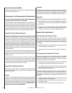
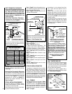
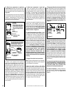
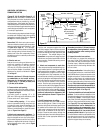
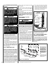
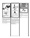
Piezo
Igniter
Gas Valve
ON/OFF Switch
Access Plate
Right Side
Modesty Panel
Hi-Lo
Extension Knob
Figure 34
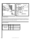
Gas
Valve
3/8" NPT x
Flare Fitting
3/8" Flex Tubing
3/8" Nipple
3/8" Union
3/8" Close Nipple
3/8" Shut-off Valve
1/2" x 3/8"
Reducer
Gas
Stub
1/2" x 3/8" Flare
Shut-off Valve
Gas Flex Line Connector
*Sediment
Trap
3"
Min
Note: The gas supply line
must be installed in accor-
dance with building codes
by a qualified installer
approved and/or licensed
as required by the locality.
In the Commonwealth of
Massachusetts, installation
must be performed by a
licensed plumber or gas
fitter.
*A Sediment Trap is recom-
mended to prevent moisture
and debris in gas line from
damaging the valve.
Figure 33 - GAS CONNECTION
E. Re-install the access plate, making certain
the gasket has not been damaged.
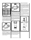
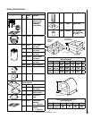
Step 7. INSTALLING CERAMIC PANELS,
LOGS AND GLOWING EMBERS
The logs are packaged in a carton and shipped
separately. Plastic bags with glowing embers,
lava rock and vermiculite are also included.
Refer to the Ceramic Panel and Log Set
Placement Supplement for detailed placement
instructions.
The gas control valve is located on the right
side of the unit.
To access the valve, remove the front door
assembly and the access plate (refer to
Figure 34).
The control valves have a 3/8" (10 mm) NPT
thread inlet port.
Secure all joints tightly using appropriate
tools and sealing compounds (ensure propane
resistant compounds are used in propane
applications).
Test all connections for gas leaks
(Factory and field):
D. Turn on burner then observe the individual
tongues of flame on the burner. Make sure
all ports are open and producing flame evenly
across the burner. If any ports are blocked, or
partially blocked, clean out the ports.