MEGAPOWER CPU 8200-0421-03, REV. G
ADMINISTRATOR’S GUIDE
41 of 82
When any member of the set is activated, all
members of the set are activated.
Each member of a wired set must be
designated as “Wired Set” or “Wired Group
Ack,” except the last member of the set, which
must be designed as “No,” “No Group Ack,”
“Salvo,” or “Salvo Group Ack.”
− No Group Ack, Yes Group Ack, Salvo Group
Ack, Wired Group Ack – When an alarm is
cleared manually by a keyboard operator, all
alarms in the wired set are cleared.
• Aux – Identifies an auxiliary device to be included
as an action when this alarm activates. Choose
from the following:
– Don’t Care – Ignores the auxiliary
– Aux 1-4 On – Activates auxiliaries 1, 2, 3, or 4
when an alarm is triggered
– Aux 1-4 Off – Deactivates auxiliaries 1, 2, 3, or
4 when an alarm is triggered
• Dwell – When the monitor is armed to sequence
alarms, the dwell time specifies how long an
alarm stays on screen before the next alarm in
queue takes its place. Options are 1-60 seconds.
• Alarm Message – Message that appears on a
given monitor when an alarm is activated. Alarm
messages are created in the Alarm – Alarm
Messages screen.
After the alarm message is created, enter the
alarm message number in the Alarm Messages
field of the Alarm – Contact Definitions screen.
• Email Message – Text of Email message
delivered to recipients designated in the Alarms –
Email messages screen (
Figure 86). A message
can be sent to any designated Email address in
the event of an alarm.
To create an Email message, click on the Email
Message field and the following appears:
− <<Add New…>> – When you select this, click
again outside this field and the following dialog
box appears (
Figure 83).
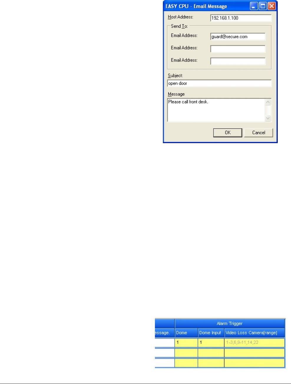
Figure 83. Email Message dialog
1. To prepare an Email message, complete the
following fields in the dialog box:
– Host Address – Enter the IP address of the
host Email server.
– Send To: – Section that allows up to three
Email addresses to be designated.
– Email Address – Enter each Email address
that you want the message to go to.
– Subject – Enter a subject line that briefly
describes the action to take in the event an
alarm occurs.
– Message – Add descriptive text that will
help the reader to understand what needs to
be accomplished.
2. Click OK to save and close the dialog box.
• Alarm Trigger – Enables the configuring of dome
input alarms. The first two columns, Dome and
Dome Input can be edited while the third column,
Video Loss Camera (range) is read-only.
Figure 84. Alarm Trigger Columns


