


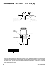
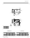
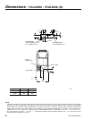
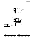
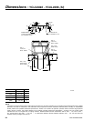
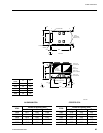
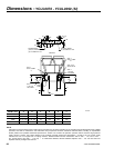
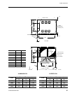
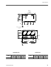
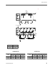
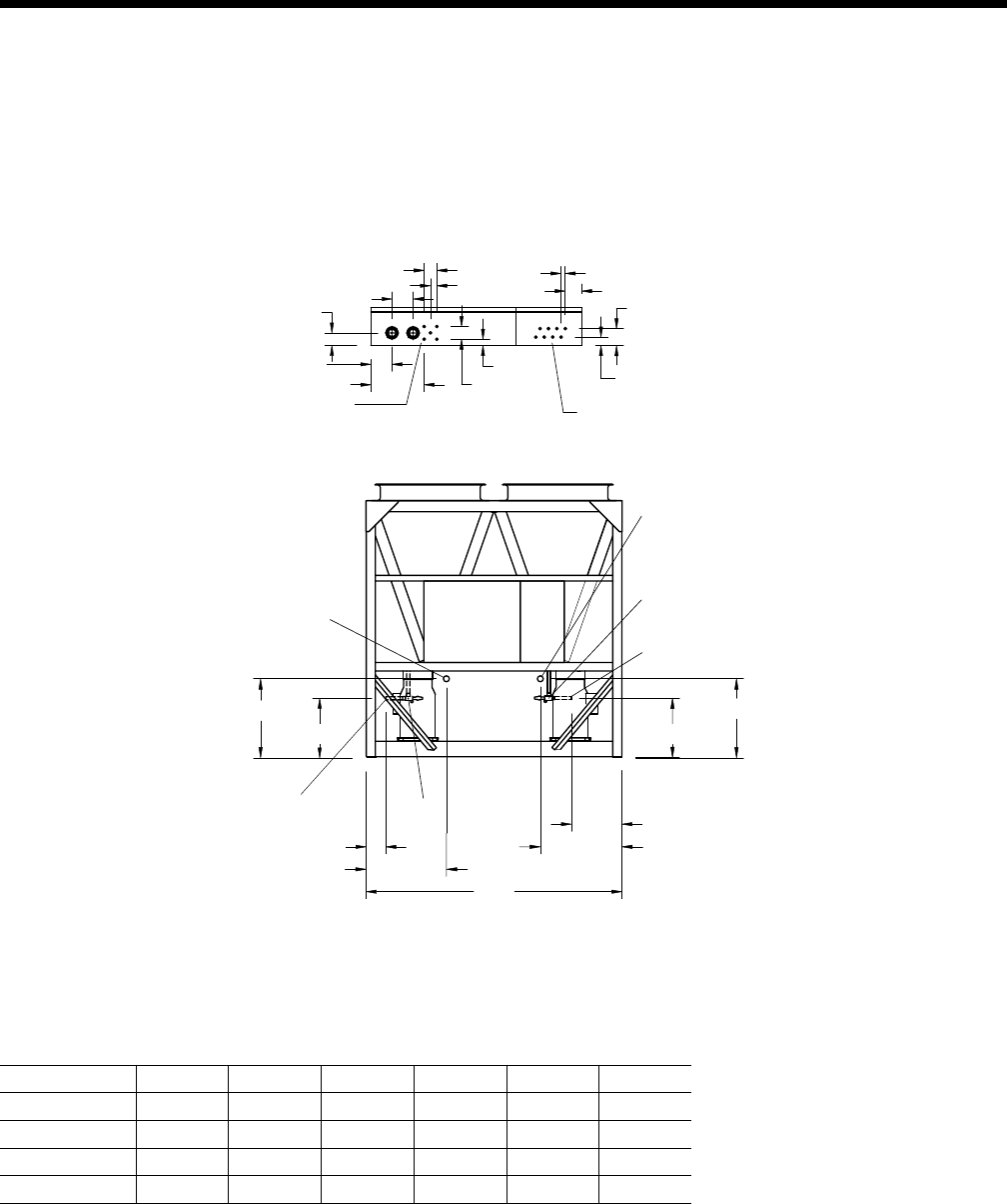
MODEL YCUL A B C D E F
0076 2 1/8” OD 2 1/8” OD 741 860 175 741
0080 2 1/8” OD 2 1/8” OD 741 860 175 741
0086 2 1/8” OD 2 1/8” OD 741 430 132 725
0090 2 5/8” OD 2 5/8” OD 725 430 132 725
YORK INTERNATIONAL
86
YORK INTERNATIONAL
87
FORM 150.63-EG1
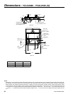
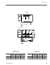
NOTE:
Placement on a level surface of free of obstructions (including snow, for winter operation) or air circulation ensures rated performance, reliable
operation, and ease of maintenance. Site restrictions may compromise minimum clearances indicated below, resulting in unpredictable
airow patterns and possible diminished performance. YORK’s unit controls will optimize operation without nuisance high-pressure
safety cutouts; however, the system designer must consider potential performance degradation. Access to the unit control center
assumes the unit is no higher than on spring isolators. Recommended minimum clearances: Side to wall – 2m; rear to wall –
2m; control panel to end wall – 1.2m; top – no obstructions allowed; distance between adjacent units – 3m. No more than one
adjacent wall may be higher than the unit.
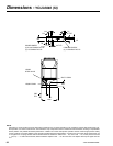
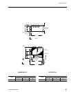
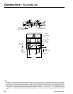
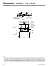
Dimensions - YCUL0076 - YCUL0090 (SI)
LD04461