


YORK INTERNATIONAL
14
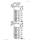
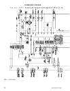
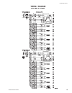
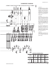
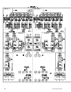
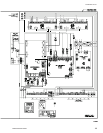
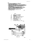
WIRING DIAGRAM
WYE-DELTA START
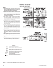
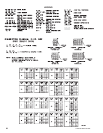
NOTES:
1. Field wiring to be in accordance with the current
edition of the National Electrical Code as well as all
other applicable codes and specifications.
2. Numbers along the right side of a diagram are line
identification numbers. The numbers at each line
indicate the line number location of relay contacts.
An unlined contact location signifies a normally closed
contact. Numbers adjacent to circuit lines are the
circuit identification numbers.
3. Any customer supplied contacts must be suitable
for switching 24VDC. (Gold contacts recom-
mended.) Control Wiring must not be run in the same
conduit with any line voltage wiring.
4. To cycle unit on and off automatically with contact
shown, install a cycling device in series with the
flow switch (FSLW). See Note 3 for contact rating
and wiring specifications. Also refer to cautions on
the following page.
5. To stop unit (Emergency Stop) with contacts other
than those shown, install the stop contact between
5 and 1. If a stop device is not installed, a jumper
must be connected between terminals 5 and 1. De-
vice must have a minimum contact rating of 100VA
at 115 volts A.C.
6. Alarm contacts are for annunciating alarm/unit mal-
function. Contacts are rated at 115V, 100VA, resis-
tive load only, and must be suppressed at load by
user.
7. See Installation, Operation and Maintenance Manual
when optional equipment is used.
8. Control panel to be securely connected to earth
ground.
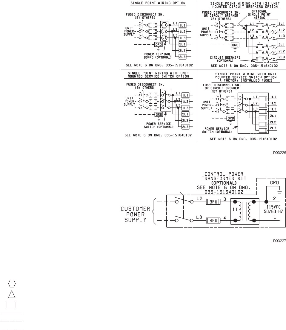
9. Us 2KVA transformer in optional transformer kit un-
less there are optional oil separator sump heaters
which necessitates using a 3KVA transformer.
FIG. 1 – ELEMENTARY DIAGRAM – WYE-DELTA START
LEGEND
Transient Voltage Suppression
Terminal Block for Customer Connections
Terminal Block for Customer Low Voltage
(Class 2) Connections. See Note 2
Terminal Block for YORK Connections Only
Wiring and Components by YORK
Optional Equipment
Wiring and/or Components by Others
T S