


FORM 201.18-W1
13
YORK INTERNATIONAL
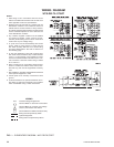
CAUTION:
No Controls (relays, etc.) should
be mounted in the Smart Panel
enclosure or connected to power
supplies in the control panel.
Additionally, control wiring not
connected to the Smart Panel
should not be run through the
cabinet. This could result in nui-
sance faults.
CAUTION:
Any inductive devices (relays)
wired in series with the flow
switch for start/stop, into the
Alarm circuitry, or pilot relays
for pump starters wired through
motor contactor auxiliary con-
tacts must be suppressed with
YORK P/N 031-00808-000 sup-
pressor across the relay/
contactor coil.
Any contacts connected to flow
switch inputs or BAS inputs on
terminals 13 - 19 or TB3, or any
other terminals, must be sup-
pressed with a YORK P/N 031-
00808-000 suppressor across
the relay/contactor coil.
CAUTION:
Control wiring connected to the
control panel should never be
run in the same conduit with
power wiring.
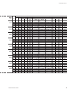
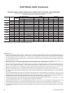
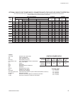
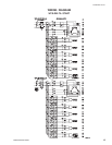
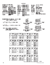
UNIT
CONTROL MIN MAX DUAL NON-FUSED
VOLTAGE
POWER CIRCUIT ELEMENT DISC.
SUPPLY AMP. FUSE SIZE SWITCH SIZE
ALL MODELS
115-1-50/60 20A 20A 250V 30A 240V
W/O TRANS.
MODELS -17 200-1-60 15A 15A 250V 30A 240V
WITH -28 230-1-60 15A 15A 250V 30A 240V
TRANS. -46 400-1-60 8A 8A 600V 30A 480V
* -58 575-1-60 8A 8A 600V 30A 600V
* All primary and secondary wiring between transformer and control panel included.
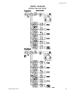
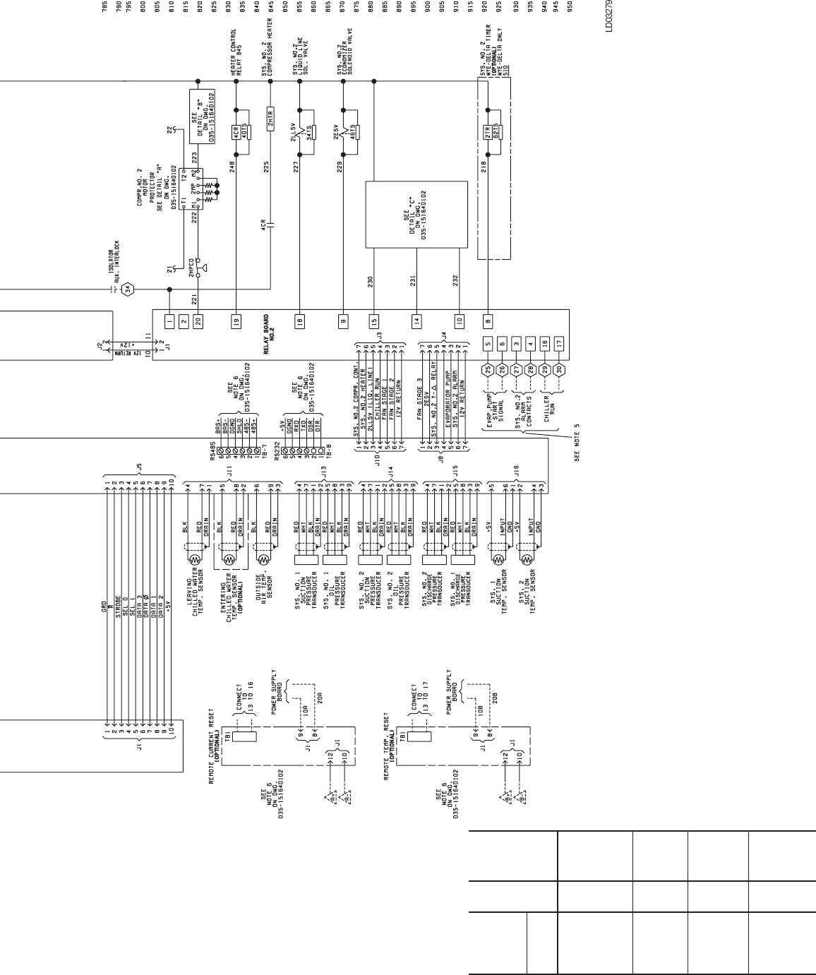
CONTROL POWER SUPPLY
ELEMENTARY DIAGRAM