


254892-YTG-C-0606
6 Unitary Products Group
All dimensions are in inches. They are subject to change
without notice. Certified dimensions will be provided upon
request.
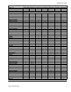
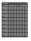
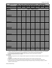
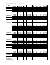
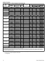
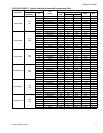
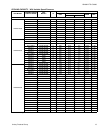
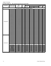
PHYSICAL AND ELECTRICAL DATA - 3 PHASE
MODEL
H1RD
030S25
H1RD
036S25
H1RD
042S25
H1RD
048S25
H1RD
060S25
H1RD
030S46
H1RD
036S46
H1RD
042S46
H1RD
048S46
H1RD
060S46
Unit Supply Voltage 208-230V, 3φ, 60Hz 460V, 3φ, 60Hz
Normal Voltage Range
1
187 to 252 432 to 504
Minimum Circuit Ampacity 14.3 14.3 12.4 21.5 23.1 6.9 9.6 6.9 10.3 11.3
Max. Overcurrent Device Amps
2
20 20 20 35 40 15 15 15 15 15
Min. Overcurrent Device Amps
3
15 15 15 25 25 15 15 15 15 15
Compressor Type
4
Recip Recip Recip ScrollB ScrollB Recip Recip Recip ScrollB ScrollB
Compressor Amps
Rated Load 10.2 10.2 8.8 16.0 17.3 4.9 13.5 11.8 7.7 8.4
Locked Rotor 72 72 72 115 123 45 45 45 50 70
Crankcase Heater No No No No No No No No No No
Fan Motor Amps Rated Load 1.5 1.5 1.5 1.5 1.5 0.7 0.7 0.7 0.7 0.7
Fan Diameter Inches 22 22 22 22 24 22 22 22 24 24
Fan Motor
Rated HP 1/4 1/4 1/4 1/4 1/4 1/4 1/4 1/4 1/4 1/4
Nominal RPM 850 850 850 850 850 850 850 850 850 850
Nominal CFM 3100 3150 3550 3550 3600 3100 3150 3550 3550 3600
Coil
Face Area Sq. Ft. 15.72 15.72 23.60 24.00 27.00 15.72 15.72 23.60 24.00 27.00
Rows Deep 1 1 1 1 1 1 1 1 2 2
Fin / Inches 22 22 22 22 22 22 22 22 18 18
Liquid Line Set OD (Field Installed) 3/8 3/8 3/8 3/8 3/8 3/8 3/8 3/8 3/8 3/8
Vapor Line Set OD (Field Installed) 3/4 7/8 7/8 7/8 1-1/8 3/4 7/8 7/8 7/8 1-1/8
Unit Charge (Lbs. - Oz.)
5
5 - 13 6 - 0 8 - 13 8 - 6 10 - 2 5 - 13 6 - 0 8 - 13 8 - 6 10 - 2
Charge Per Foot, Oz. 0.68 0.70 0.70 0.70 0.76 0.68 0.70 0.70 0.70 0.76
Operating Weight Lbs. 208 208 208 215 294 208 208 215 250 294
1. Rated in accordance with ARI Standard 110, utilization range “A”.
2. Dual element fuses or HACR circuit breaker. Maximum allowable overcurrent protection.
3. Dual element fuses or HACR circuit breaker. Minimum recommended overcurrent protection.
4. All scrolls listed with a superscript “B” are Bristol scrolls. All scrolls listed with a superscript “C” are Copeland scrolls.
5. The Unit Charge is correct for the outdoor unit, matched indoor coil and 15 feet of refrigerant tubing. For tubing lengths other than
15 feet, add or subtract the amount of refrigerant, using the difference in length multiplied by the per foot value.
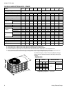
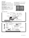
C
A
B
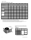
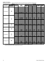
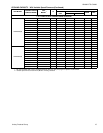
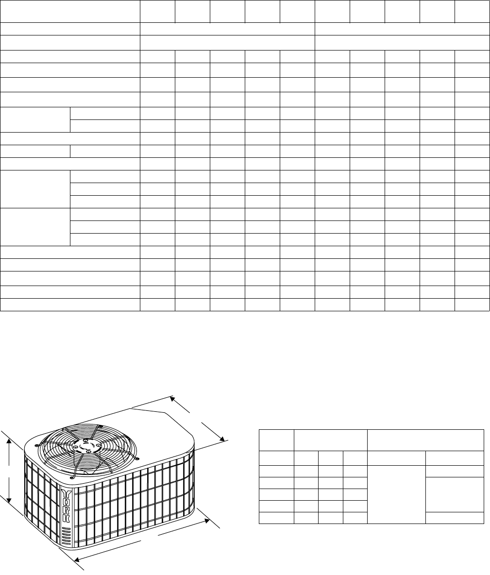
DIMENSIONS
Unit
Model
Dimensions
(Inches)
Refrigerant Connection
Service Valve Size
A
1
1. Including Fan Guard.
* Adapter fitting required for 1-1/8” line set.
B C Liquid Vapor
030 27 37 27
3/8”
3/4”
036 27 37 27
7/8”042 39 37 27
048 34 43 32
060 38 43 32 7/8”*