


268890-UIM-B-0607
Unitary Products Group 7
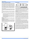
RESIDENTIAL AND NON HUD MODULAR HOME
DOWNFLOW AND HORIZONTAL RETURN PLENUM
CONNECTION
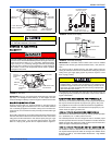
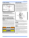
The return duct system must be connected to the furnace inlet and the
return duct system must terminate outside the space containing the fur-
nace. When replacing an existing furnace, if the existing plenum is not
the same size as the new furnace then the existing plenum must be
removed and a new plenum installed that is the proper size for the new
furnace.
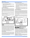
Attach the return plenum to the furnace inlet duct flanges. This is typi-
cally through the use of S cleat material when a metal plenum is used.
The use of an approved flexible duct connector is recommended on all
installations. The connection of the plenum to the furnace and all the
ducts connecting to the plenum must be sealed to prevent air leakage.
The sheet metal should be crosshatched to eliminate any popping of
the sheet metal when the indoor fan is energized.
The duct system is a very important part of the installation. If the duct
system is improperly sized the furnace will not operate properly. The
ducts attached to the furnace must be of sufficient size so that the fur-
nace operates at the specified external static pressure and within the air
temperature rise specified on the nameplate.
Attic installations must meet all minimum clearances to combustibles
and have floor support with required service accessibility.
IMPORTANT: If an external mounted filter rack is being used see the
instructions provided with that accessory for proper hole cut size.
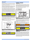
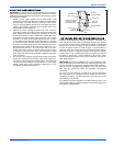
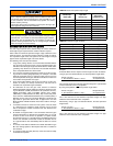
SECTION III: FILTERS
FILTER INSTALLATION
All applications require the use of a filter. Replacement filter size is
shown in Table 5.
NOTES:
1. Air velocity through throwaway type filters may not exceed 300 feet
per minute. All velocities over this require the use of high velocity fil-
ters.
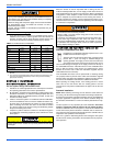
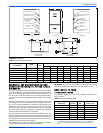
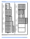
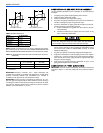
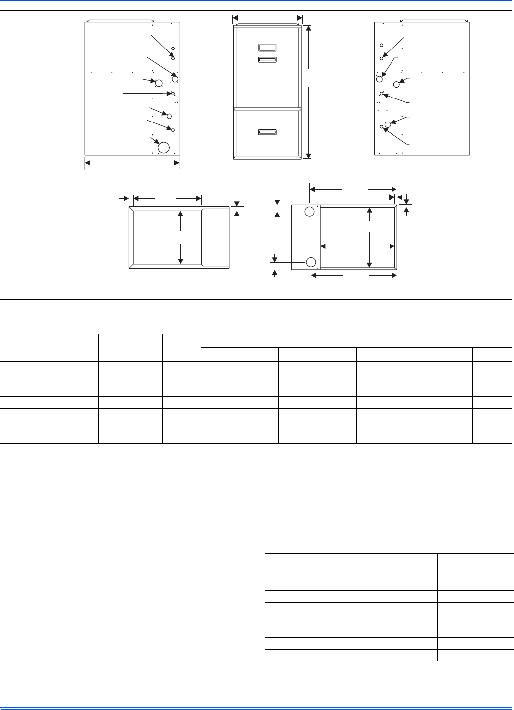
FIGURE 3: Dimensions
C
19-1/4
1-1/4
1-1/4
5/8
5/8
23-5/8
D
2-1/4
23-1/4
20
B
BOTTOM IMAGE
SUPPLY END
TOP IMAGE
RETURN END
LEFT SIDE
RIGHT SIDE
HORIZONTAL CONDENSATE
DRAIN OPENING 2”
JUNCTION BOX
HOLE 7/8”
GAS PIPE ENTRY 1-1/2”
CONDENSATE DRAIN
HOLE 7/8”
SIDE PIPING HOLE3-3/8”
T-STAT WIRING7/8” K.O.
HORIZONTAL CONDENSATE
DRAIN OPENING 1-3/4”
28-1/2
T-STAT WIRING7/8” K.O.
HORIZONTAL CONDENSATE
DRAIN OPENING 1-3/4”
HORIZONTAL
CONDENSATE
DRAIN OPENING 1-3/4”
JUNCTION BOX
HOLE 7/8”
GAS PIPE
ENTRY1-1/2”
CONDENSATE DRAIN
HOLE 7/8”
40
A
FRONT
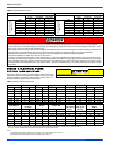
TABLE 4:
Cabinet and Duct Dimensions
BTUH (kW)
Input/Output
CFM
Cabinet
Size
Cabinet Dimension
A (in.) A (cm) B (in.) B (cm) C (in.) C (cm) D (in.) D (cm)
40/37 (11.7/10.8) 1200 (34.0) A 14-1/2 36.8 13-1/4 33.7 12 30.5 1-3/4 4.44
60/56 (17.6/16.4) 1200 (34.0) B 17-1/2 44.4 16-1/4 41.3 15 38.1 1-3/4 4.44
80/75 (23.4/22.0) 1200 (34.0) B 17-1/2 44.4 16-1/4 41.3 15 38.1 1-3/4 4.44
80/75 (23.4/22.0) 1600 (45.3) C 21 53.3 19-3/4 50.2 18-1/2 47.0 2-1/8 5.40
100/95 (29.3/27.8) 1600 (45.3) C 21 53.3 19-3/4 50.2 18-1/2 47.0 2-1/8 5.40
100/95 (29.3/27.8) 2000 (56.6) C 21 53.3 19-3/4 50.2 18-1/2 47.0 2-1/8 5.40
120/112 (35.1/32.8) 2000 (56.6) D 24-1/2 62.2 23-1/4 59.1 22 55.9 2-1/2 6.35
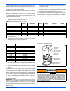
TABLE 5:
Recommended Filter Sizes
Input / Output
BTU/H (kW)
CFM
(m
3
/min)
Cabinet
Size
Top Return
Filter in(cm)
40 (11.7) 1200 (34) A (2) 14 x 20 (36 x 51)
60 (17.8) 1200 (34) B (2) 14 x 20 (36 x 51)
80 (23.4) 1200 (34) B (2) 14 x 20 (36 x 51)
80 (23.4) 1600 (45) C (2) 14 x 20 (36 x 51)
100 (29.3) 1600 (45) C (2) 14 x 20 (36 x 51)
100 (29.3) 2000 (57) C (2) 14 x 20 (36 x 51)
120 (35.1) 2000 (57) D (2) 14 x 20 (36 x 51)