


268890-UIM-B-0607
Unitary Products Group 35
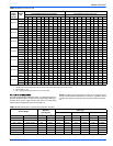
ADJUSTMENT OF TEMPERATURE RISE
The temperature rise, or temperature difference between the return air
and the heated supply air from the furnace, must be within the range
shown on the furnace rating plate and within the application limitations
as shown in Table 7.
After about 20 minutes of operation, determine the furnace temperature
rise. Take readings of both the return air and the heated air in the ducts,
about six feet (1.83 m) from the furnace where they will not be affected
by radiant heat. Increase the blower speed to decrease the temperature
rise; decrease the blower speed to increase the rise.
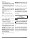
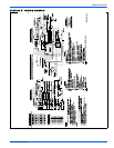
All direct-drive blowers have multi-speed motors. The blower motor
speed taps are located in the control box in the blower compartment.
Refer to Figure 40, and the unit-wiring label to change the blower
speed. To use the same speed tap for heating and cooling, the heat ter-
minal and cool terminal must be connected using a jumper wire and
connected to the desired motor lead. Place all unused motor leads on
Park terminals. Two are provided.
ADJUSTMENT OF FAN CONTROL SETTINGS
This furnace is equipped with a time-on/time-off heating fan control. The
fan on delay is fixed at 30 seconds. The fan off delay has 4 settings (60,
90, 120 and 180 seconds). The fan off delay is factory set to 120 sec-
onds. The fan-off setting must be long enough to adequately cool the
furnace, but not so long that cold air is blown into the heated space. The
fan-off timing may be adjusted by positioning the jumper on two of the
four pins as shown in Figure 40.
The blower speed connections shown in Figure 40 are typical. How-
ever, these connections may vary from model to model and may be
changed as needed to give proper heating and cooling airflow.
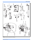
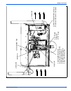
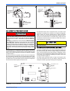
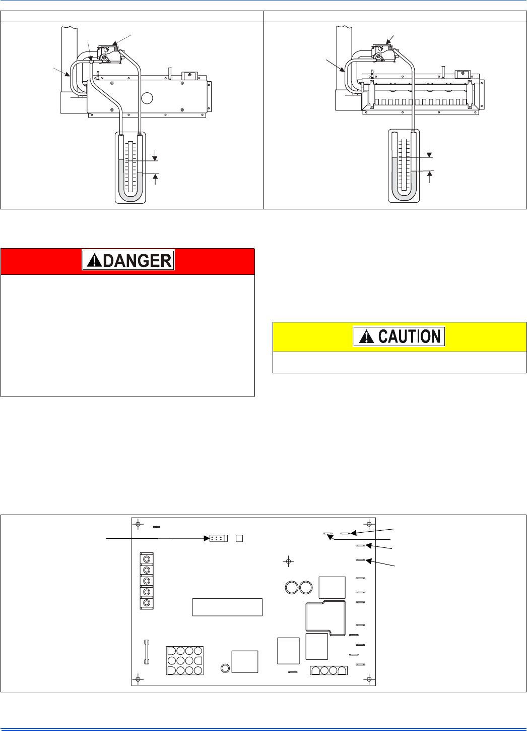
WITH BURNER BOX COVER IN PLACE WITH BURNER BOX COVER REMOVED
FIGURE 39: Reading Gas Pressure
6
5
4
3
2
1
0
1
2
3
4
5
6
6
5
4
3
2
1
0
1
2
3
4
5
6
3.5 IN
WATER COLUMN
GAS PRESSURE
SHOWN
U-TUBE
MANOMETER
GAS
VALVE
BURNER BOX
PRESSURE
REFERENCE
HOSE
TEE
FITTING
6
5
4
3
2
1
0
1
2
3
4
5
6
6
5
4
3
2
1
0
1
2
3
4
5
6
3.5 IN
WATER COLUMN
GAS PRESSURE
SHOWN
U-TUBE
MANOMETER
GAS VALVE
BURNER BOX
PRESSURE
REFERENCE
HOSE
The temperature rise, or temperature difference between the return
air and the supply (heated) air from the furnace, must be within the
range shown on the furnace rating plate and within the application
limitations shown in Table 7 “ELECTRICAL AND PERFORMANCE
DATA”.
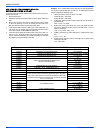
The supply air temperature cannot exceed the “Maximum Supply
Air Temperature” specified in these instructions and on the fur-
nace rating plate. Under NO circumstances can the furnace be
allowed to operate above the Maximum Supply Air Temperature.
Operating the furnace above the Maximum Supply Air Temperature
will cause premature heat exchanger failure, high levels of Carbon
Monoxide, a fire hazard, personal injury, property damage, and/or
death.
Do not energize more than one motor speed at a time or damage to
the motor will result.
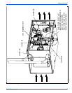
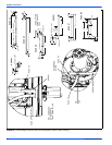
FIGURE 40: Furnace Control Board
PARK
PARK
HI COOL
HEAT
EAC-H
L1
XFMR
NEUTRALS
HUM
TWIN
60
90
120
180
BLOWER
OFF
DELAY
Y/Y2
W
R
G
C
FAN OFF
ADJUSTMENT
JUMPER
RED-LOW
YELLOW-MED. LOW
BLACK-HI
BLUE-MED. HI