


268890-UIM-B-0607
Unitary Products Group 23
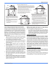
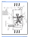
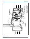
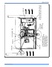
Horizontal Left Air Flow (Inducer Low) -
Refer to Figures 31 & 32
1. Remove all the condensate hoses inside the furnace, leaving the
3/8" barbed nipple and hose # 4, both factory installed, in the rain
gutter.
2. Remove the condensate trap and its bracket from inside the fur-
nace, saving the screws for use later.
3. Remove the yellow cap from the top drain of the rain gutter and
install loosely packed 3/8" barbed nipple in it.
4. Remove the large condensate cap from the side of the condensate
pan and install it on the middle drain of the condensate pan, from
where #1 hose was removed.
5. Install longer dogleg end of hose #10 through the casing hole on to
the side drain of the condensate pan, where cap was removed in
step #4. Some lubricant may have to be used to facilitate this
installation as the hose is designed as a tight fit over the conden-
sate drain. The other, shorter, dogleg end of hose #10 should be
installed into the large recessed drain in the condensate trap.
6. Install the condensate trap bracket, with the condensate trap, on to
the front side of the furnace, using the screws removed in step #1.
7. Switch the blocked condensate hose to the condensate tap on the
bottom of the condensate pan (close to the inducer).
8. Install hose #9 between the external drain on the Wye and the
condensate trap; with the dogleg end installed on the protruded
(stub) drain of the condensate trap. The length of hose #9 may
have to be trimmed to ensure proper condensate drainage.
9. Remove all condensate hoses off the 3/8" barbed tee.
10. Cut 1-1/2" length of straight 3/8" hose off of hose #5 and install it
on the 3/8" barbed tee. The other end of the 1-1/2" hose should be
installed on the welled opening on the condensate trap.
11. Install one end of the 3/8" barbed tee on hose #4 as shown.
Ensure that hose #4 follows a gradual downward slope all the way
to the barbed tee.
12. Install hose #6 between the top drain of the rain gutter of the
inducer and the remaining open end of 3/8" barbed tee.
13. Ensure that all hoses are properly installed, have no kinks, and are
draining properly. All hoses on the condensate trap should be
pushed all the way down to ensure against leakage.
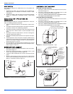
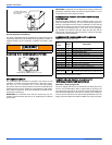
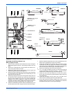
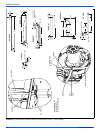
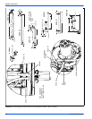
FIGURE 30: Downflow Condensate Drain Hose Configuration
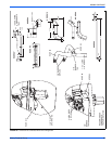
HOSE #9
3/4”
1-5/8”
33”
3/4”
HOSE #2
3/8”
17-1/2”
SPRING CLAMP
3/4”
DOG
LEG
HOSE #8
1”
22-1/8”
SPRING CLAMP
2-3/4”
1”
DOG
LEG
* USED AFTER
CONDENSATE
TRAP
HOSE #4
2”
3/4”
1/2”
SPRING CLAMP
HOSE #2 (if drain aligned
above the hole in
furnace top)
HOSE #4 (with 3/8”
barbed nipple)
HOSE #5
HOSE #1
HOSE #3
3/8” Barbed Tee
HOSE #5
SPRING CLAMP
9”
3/4”
3/4”
SPRING CLAMP
HOSE #3
3-3/8”
5/8”
1-1/8”
1”
2-3/4”
8-1/8”
HOSE #1
DOGLEG
SPRING CLAMP
-
CUT
4-1/2”
PIECE