


268890-UIM-B-0607
Unitary Products Group 11
SUPPLY VOLTAGE CONNECTIONS
IMPORTANT: The power connection leads and wiring box may be relo-
cated to the left side of the furnace. Remove the screws and cut wire tie
holding excess wiring. Reposition on the left side of the furnace and fas-
ten using holes provided.
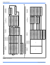
1. Provide a power supply separate from all other circuits. Install
overcurrent protection and disconnect switch per local/national
electrical codes. The switch should be close to the unit for conve-
nience in servicing. With the disconnect or fused switch in the OFF
position, check all wiring against the unit wiring label. Refer to the
wiring diagram shown in Figure 41.
2. Remove the screws retaining the junction box cover. Route the
power wiring through the opening in the unit into the junction box
with a conduit connector or other proper connection. In the junc-
tion box there will be three wires, a Black Wire, a White Wire and a
Green Wire. Connect the power supply as shown on the unit-wir-
ing label on the inside of the blower compartment door or Figure
10. The black furnace lead must be connected to the L1 (hot) wire
from the power supply. The white furnace lead must be connected
to neutral. Connect the green furnace lead (equipment ground) to
the power supply ground. An alternate wiring method is to use a
field provided 2” (5.08 cm) x 4” (10.2 cm) box and cover on the
outside of the furnace. Route the furnace leads into the box using
a protective bushing where the wires pass through the furnace
panel. After making the wiring connections replace the wiring box
cover and screws.
3. The furnace's control system requires correct polarity of the power
supply and a proper ground connection. If the power supply polar-
ity is reversed, the control board will flash 9 times. The furnace will
not operate until the polarity is corrected. Refer to “Furnace Diag-
nostics” section of the “User’s Information, Maintenance, & Ser-
vice Manual” provided with this furnace.
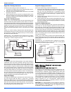
LOW VOLTAGE CONTROL WIRING CONNECTIONS
Install the field-supplied thermostat by following the instructions that
come with the thermostat. With the thermostat set in the OFF position
and the main electrical source disconnected, connect the thermostat
wiring from the wiring connections on the thermostat to the terminal
board on the ignition module, as shown in Figure 11. Electronic thermo-
stats may require the common wire to be connected as shown with the
dashed line in Figure 11. Apply strain relief to thermostat wires passing
through cabinet. If air conditioning equipment is installed, use thermo-
stat wiring to connect the Y and C terminals on the furnace control
board to the yellow and brown wires on the condensing unit (unit out-
side). Refer to Figure 11.
IMPORTANT: Set the heat anticipator in the room thermostat to 0.45
amps. Setting it lower will cause short cycles. Setting it higher will cause
the room temperature to exceed the set points.Some electronic thermo-
stats do not have adjustable heat anticipators. They may have other
type cycle rate adjustments. Follow the thermostat manufacturer's
instructions.
The 24-volt, 40 VA transformer is sized for the furnace components
only, and should not be connected to power auxiliary devices such as
humidifiers, air cleaners, etc. The transformer may provide power for an
air conditioning unit contactor.
For additional connection diagrams for all UPG equipment refer to “Low
Voltage System Wiring” document available online at www.upgnet.com
in the Product Catalog Section.
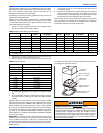
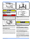
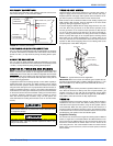
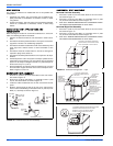
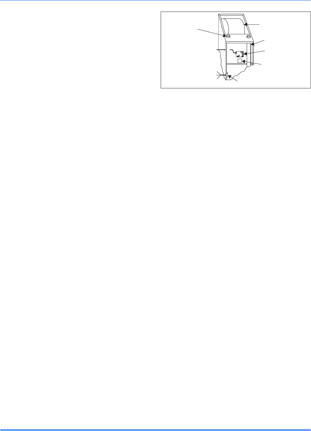
FIGURE 10: Electrical Wiring
(BLK) LI (HOT)
(WHT) N
(GRN)GND
JUNCTION
BOX
TRANSFORMER
BLOWER
COMPARTMENT
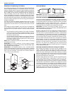
CLASS 2 SYSTEM
CONTROL WIRING
TO THERMOSTAT
COMBUSTION
AIR
VENT PIPE
IGNITION
MODULE