


268890-UIM-B-0607
38 Unitary Products Group
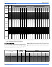
APPLYING FILTER PRESSURE DROP TO
DETERMINE SYSTEM AIRFLOW
To determine the approximate airflow of the unit with a filter in place, fol-
low the steps below:
1. Select the filter type.
2. Determine the External System Static Pressure (ESP) without the
filter.
3. Select a filter pressure drop from the table based upon the number
of return air openings or return air opening size and add to the
ESP from Step 2 to determine the total system static.
4. If total system static matches a ESP value in the airflow table (i.e.
0.20, 0.60, etc,) the system airflow corresponds to the intersection
of the ESP column and Model/Blower Speed row.
5. If the total system static falls between ESP values in the table (i.e.
0.58, 0.75, etc.), the static pressure may be rounded to the nearest
value in the table determining the airflow using Step 4 or calculate
the airflow by using the following example.
Example: For a 120,000 Btuh furnace operating on high speed blower,
it is found that total system static is 0.58" w.c. To determine the system
airflow, complete the following steps:
1. Obtain the airflow values at 0.50" & 0.60" ESP.
Airflow @ 0.50": 2152 CFM
Airflow @ 0.60": 2042 CFM
2. Subtract the airflow @ 0.50" from the airflow @ 0.60" to obtain air-
flow difference.
2042 - 2152 = -110 CFM
3. Subtract the total system static from 0.50" and divide this differ-
ence by the difference in ESP values in the table, 0.60" - 0.50", to
obtain a percentage.
(0.58 - 0.50) / (0.60 - 0.50) = 0.8
4. Multiply percentage by airflow difference to obtain airflow reduc-
tion.
(0.8) x (-110) = -88
5. Subract airflow reduction value to airflow @ 0.50" to obtain actual
airflow @ 0.58" ESP.
2152 - 88 = 2064
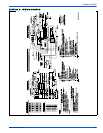
FIELD INSTALLED ACCESSORIES - NON-ELECTRICAL
MODEL NO. DESCRIPTION USED WITH
1NP0347 PROPANE (LP) CONVERSION KIT ALL MODELS
1CT0302 CONCENTRIC INTAKE/VENT 2” ALL MODELS EXCEPT 120 MBH
1CT0303 CONCENTRIC INTAKE/VENT 3” ALL MODELS
1PS0904
HIGH ALTITUDE PRESSURE SWITCH KIT
(Does Not Include Orifices)
40
1PS0901 60/100/120
1PS0902 80/1200
1PS0903 80/1600
1NK0301 CONDENSATE NEUTRALIZER KIT ALL MODELS
1HT0901 SIDEWALL VENT TERMINATION KIT 3” ALL MODELS
1HT0902 SIDEWALL VENT TERMINATION KIT 2” ALL MODELS
1CB0314 COMBUSTIBLE FLOOR BASE
These kits are required in downflow application when using G*F*
series coils. These kits are not required with MC/FC series coils,
but please ensure that the coil and furnace are secured and that
there are noair leaks.
14-1/2” CABINET
1CB0317 17-1/2” CABINET
1CB0321 21” CABINET
1CB0324 24 1/2” CABINET
1TK0914
COIL TRANSITION KIT
14-1/2” CABINET
1TK0917 17-1/2” CABINET
1TK0921 21” CABINET
1TK0924 24 1/2” CABINET
1VK0901 3-WAY TRANSITION KIT All MODELS