


4. After the disc has been removed, burnish the external sur
-
faces and clean the internal surfaces as outlined above.
5. Movethe drynitrogen supplyback tothe accessport onthe
liquid line service valve.
6. Braze the liquid line to the liquidconnection on theindoor unit
while maintaining a minimum flow of dry nitrogen through the
liquid line, the indoor coil and the hole in the vapor disc.
7. Unbraze the discon the vapor connectionof the indoor unit
while maintaining the flow of dry nitrogen.
8. After the disc has been removed, burnish the external sur
-
faces and clean the internal surfaces as outlined above.
Thevaporpiping cannowbebrazedtothe vaporconnectionon
the indoor unit while maintaining a minimum flow of dry nitro
-
gen.
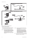
Before brazingthe vaporline tothe outdoorunit, makesure the
refrigerant in the line has been recovered, then remove the
copper disc from its vapor connection per the following proce
-
dure:
1. Make sure that the vapor line service valve on the outdoor
unit is front-seated and closed with its valve stem in the
maximum clockwise position.
2. Drilla smallhole throughthe discbefore unbrazingit toper
-
mit a flow of dry nitrogen through the connection while its
being unbrazed.
3. Move the dry nitrogen supply to the access port on the va-
por line service valve of the outdoor unit.
4. Unbraze the disc on the vapor line connection of the out-
door unit while maintaining a minimum flow of dry nitrogen
through the access port of the vapor line service valve and
the hole in the vapor disc.
5. After the disc has been removed, burnish the external sur-
faces and clean the internal surfaces of the vapor connec-
tion and the vapor piping.
The vapor line can now be brazed to the vapor connection on
the outdoor unit while maintaining the flow of dry nitrogen.
After the liquid andvapor lines have been installed, thesystem
should be evacuated and charged.
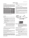
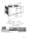
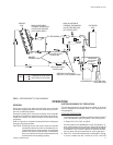
EXTENDING THE SERVICE PORTS
(Refer to Fig. 5)
1. Loosen thescrews thatsecure theservice portsin shipping
position.
2. Push the service ports through the corner post.
3. Tighten the screws to secure the service ports for installa
-
tion.
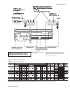
EVACUATING AND CHARGING
With the liquid and suction line service valves closed, connect
a vacuum pump through a charging manifold to the access
ports on both the liquid and suction line service valves.
NOTE: The vacuum pump connections should be short and
no smaller than 3/8" O.D.
Therefrigerant linesandtheevaporatorcoil cannowbeevacu
-
ated to 500 Microns without disturbing the charge in the con
-
denser coil or the compressor.
After proper evacuation and dehydration, charge refrigerant
throughthe accessport onthe liquidlineservice valveallowing
the vacuum to draw in as much refrigerant as possible.
CAUTION: Do not charge liquid refrigerant through the com
-
pressor suction connection.
CAUTION: Do not attempt to start the compressor without at
least 8 hours of crankcase heat or compressor
damage will occur.
to continue charging refrigerant, open the liquid and the suction
line service valves fully. Turn the stem of the liquid service valve
clockwise 1/4 turn to open its access port for reading pressure.
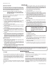
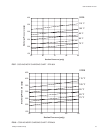
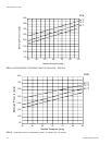
Startthe compressor(after8 hoursof crankcaseheat), turnthe
stemofthe suctionlineservicevalve clockwise1/4turnto open
its service port and continue to charge refrigerant gas through
thissuction accessport untilyou meettheconditions shownon
the charging curve, Figures 7 through 15.
Open theliquid and vaporline service valvesfully to closetheir
access ports after the system has been charged.
BALANCE POINT SETTING
The balance point of a heat pump is the lowest temperature at
which the refrigeration system can heat the building without
any supplemental resistance heat.
The balance point is dependent upon -
1. The outdoor design temperature,
2. The building heat loss at the outdoor design temperature,
and
3. The heating capacity of the system at the outdoor design
temperature.
Unitary Products Group 9
035-16192-001-A-1001