


LIMITATIONS
These units must be installed in accordance with all national
andlocal safetycodes. Ifno localcodesapply,installation must
conform with the appropriate national codes. See Table 1 for
unit application data. Units are designed to meet National
SafetyCodeStandards.Ifcomponentsare tobeaddedtoa unit
to meet local codes, they are to be installed at the dealer's
and/or the customer's expense.
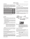
LOCATION
Use the following guidelines to select a suitable location for
these units.
1. The outdoor units must be installed outside the building.
The outdoorfansare thepropeller typeand arenot suitable
for use with duct work.
2. The outdoor and indoor units should be installed as close
together as possible and with a minimum number of bends
in the refrigerant piping. Refer to REFRIGERANT PIPING
for additional information.
3. The outdoor unit should not be installed beneath windows
orbetween structureswhere normaloperating soundsmay
be objectionable.
WARNING: The outdoor unit should not be installed in an area
where mudand/or ice could causepersonal injury.
Remember that condensate will drip from the un
-
derside ofthe unit coilsduring heat anddefrost cy
-
cles and that this condensate will freeze when the
temperature of the outdoor air is below 32 F.
4. Allunitsrequire certainclearances forproperoperationand
service.
On either rooftop or ground level installations, rubber padding
can be applied between the base rails and their supports to
lessen any transmission of vibration.
ROOF-TOP LOCATIONS
Becareful nottodamagethe roof.Consultthe buildingcontrac
-
tororarchitect iftheroofisbonded.Choose alocationwithade
-
quate structural strength to support the unit.
The unit must be mounted on solid level supports. The sup
-
ports can be channel iron beams or wooden beams treated to
reduce deterioration.
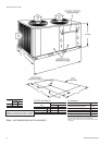
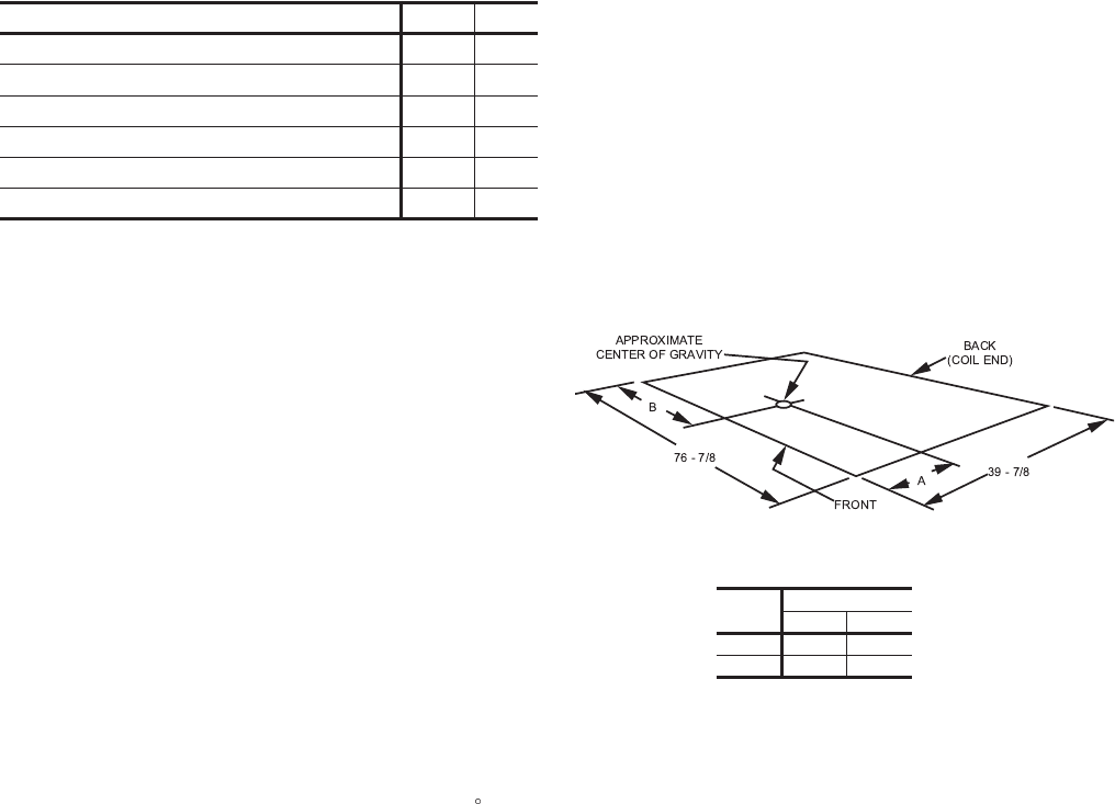
Aminimum of two (2) beams are required to support each unit.
The beams should: (1) Be positioned perpendicular to the roof
joists.(2)Extendbeyond thedimensionsoftheunit todistribute
the load on the roof, (3) Be capable of adequately supporting
the entireunitweight. Referto Figure1 andTable 2for loaddis
-
tribution and weights.
Thesebeamscanusually besetdirectlyontheroof. Flashingis
not required.
NOTE: On bonded roofs, check for special installation re
-
quirements.
GROUND LEVEL LOCATIONS
The units must be installed on a substantial base that will not
settle. Any strain on the refrigerant lines may cause a refriger
-
antleak. Aone-piececoncreteslab withfooters thatextendbe
-
low the frost line is recommended. The slab should not be tied
tothe buildingfoundation becausenoise andvibration willtele
-
graph.
A unit can also be supported by concrete piers. These piers
should: (1) extendbelow the frostline, (2) be locatedunder the
unit's four corners and (3) be sized to carry the entire unit
weight. Refer to Figure 1 and Table 2 for the center of gravity
and unit weight.
Agravel bed or some other means of handling the condensate
that willdrop fromthe underside ofthe unit coilduring theheat
-
ing and defrost cycles may have to be provided.
CAUTION: Care should be taken to protect the unit from
tampering and unauthorized persons from injury.
Screws on access panels will prevent casual
tampering. Additional safety precautions such as
fences around the unit or locking devices on the
panels may be advisable. Check local authori
-
ties for safety regulations.
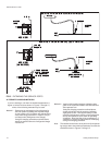
RIGGING AND HANDLING
Exercise care when moving the unit. Do not remove any pack
-
aging until the unit is near the place of installation.
Rig the unitby attaching chain orcable slings with hooksto the
round lifting holes provided in the base rails.
CAUTION: Spreaders, longer than the largest dimension
across the unit, MUST be used across the top of
the unit. See Figure 2.
WARNING: BEFORE LIFTING A UNIT, MAKE SURE THAT
ITS WEIGHT IS DISTRIBUTED EQUALLY ON
THE CABLES SO THAT IT WILL LIFT EVENLY.
Units may also be moved or lifted with a fork-lift from the front,
rear or the compressor end only through the slotted openings
provided in the base rails.
Unitary Products Group 3
035-16192-001-A-1001
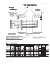
INSTALLATION
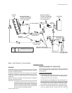
FIG. 1 - CENTER OF GRAVITY
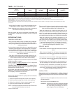
APPLICATION LIMITATIONS MIN MAX
Voltage Variation (208/230-3-60) - Volts
2
187 253
Voltage Variation (460-3-60) - Volts
2
414 506
Ambient Air on Outdoor Coil (Cooling Cycle) - °F 45 115
Ambient Air on Indoor Coil (Cooling Cycle) - °F 68 86
Ambient Air on Outdoor Coil (Heating Cycle) - °F 0
1
70
Ambient Air on Indoor Coil (Heating Cycle) - °F 60 80
TABLE 1 - UNIT APPLICATION DATA
1
Rated in accordance with ARI Standard 110, utilization range “A”.
2
Below 0 °F, the control circuit will lock out the compressor and allow the
electric heat accessory to cycle at its standby capacity.
Unit
Dim. (in.)
AB
15 Ton 16 38
20 Ton 16 38