


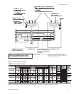
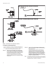


through the defrost control boards and safety switches to
energize relays RY1 and RY2, which in turn will energize
contactors 1M& 3M, startingthe compressors. Contactors
2Mand4M areenergizedthroughtheNOcontactsonauxil
-
iary contactors 1M-AUX and 3M-AUX in order to start the
outdoor fan motors.
4. Relays RY1 and RY2 prevent the electric heat accessory
referenced as standby electric heat from being utilized
whenever the compressor is in operation. This part of the
circuit is covered under HEATING OPERATION.
5. The thermostat will cycle the unit to satisfy the cooling re
-
quirements of the conditioned space.
6. After the unithas shutdown from a coolingcycle or a power
interruption, the anti-short cycle feature of the defrost con
-
trol board will not permit the unit to restart for 5 minutes.
This feature prevents the unit from short cycling.
7. Ifthe dischargepressurereaches 398psig,theHP1 orHP2
control will open and the defrost control board will lock out
the compressor. If the discharge temperature reaches
255°F, TH2 or TH4 thermostat will open and the defrost
control board will lock out the compressor. If the suction
pressurefalls to7psig,LP1or LP2willopen andthedefrost
control board will lock out the compressor.
8. If the control that caused the lockout has automatically re
-
set, the unit can be restarted by one of the following:
a. Turning the system switch on the thermostat to the
“OFF” position and back to the “COOLING” position.
b. Increasing the set point on the thermostat above the
temperature in the conditioned space and then return-
ing it to its original setting.
c. Openingand closingthe powersupply maindisconnect
switch.
IN ALL THREE RESET METHODS DESCRIBED ABOVE,
AFIVE MINUTE TIME DELAYWILL TAKE PLACE AFTER
THE RESET BEFORE THE UNIT WILL RESTART.
HEATING OPERATION
1. Reversing valve is de-energized and the system will be in
the heating mode.
2. Ifthe fanswitch onthe thermostat isin the“ON”position, in
-
door section blower motor contactor 10M will be energized
through terminalG to providecontinuous bloweroperation.
If the switch is in “AUTO” position, the blower will operate
only when thermostat calls for heating operation.
3. When TH1 of the thermostat closes for first-stage heat, a
circuit is made for the Y terminal on DC1 and DC2 through
the defrost control boards and safety switches to energize
relays RY1 and RY2, which in turn will energize contactors
1M and 3M, starting the compressors. Contactors 2M and
4Mareenergized throughtheNOcontactson auxiliarycon
-
tactors 1M-AUX and 3M-AUX in order to start the outdoor
fan motors.
4. The thermostat will cycle the unit to satisfy the heating re
-
quirements of the conditioned space.
5. After theunit has shutdownfrom aheating cycle ora power
interruption, the anti-short cycle feature of the defrost con
-
trol board will not permit the unit to restart for 5 minutes.
This feature prevents the unit from short cycling.
6.
Ifthedischarge pressurereaches398psig,theHP1or HP2
control will open and the defrost control board will lock out
the compressor. If the discharge temperature reaches
255°F, TH2 or TH4 thermostat will open and the defrost
control board will lock out the compressor. If the suction
pressurefallsto 7psig,LP1 orLP2willopenandthe defrost
control board will lock out the compressor.
7. If the control that caused the lockout has automatically re
-
set, the unit can be restarted by one of the following:
a. Turning the system switch on the thermostat to the
“OFF” position and back to the “HEATING” position.
b. Decreasing the set point on the thermostat below the
temperature in the conditioned space and then return
-
ing it to its original setting.
c. Openingandclosing thepowersupply maindisconnect
switch.
IN ALL THREE RESET METHODS DESCRIBED
ABOVE, A FIVE MINUTE TIME DELAY WILL TAKE
PLACE AFTER
THE RESET BEFORE THE UNIT WILL
RESTART.
8. Standby electric heat will be controlled by second stage
TH2 ofthe thermostatand is controlledthrough lowvoltage
terminal W1. The standby portion of electric heat cannot
operate because relays RY1 and RY2 are energized,
opening the circuit to W1, whenever the compressor is op-
erating.
9. When second stage heating TH2 is satisfied, the standby
heaters will be de-energized.
DEFROST CYCLE
When condensate freezes on the outdoor coil during heating
operation, it must be defrosted before it blocks the flow of air
across the coil.
1. Adefrost cyclewillbeinitiatedby thedefrostcontrolboard's
demand defrost feature which senses both time and out
-
door coil temperatures.
2. When the defrost cycle is initiated, the unit operates as fol
-
lows:
a. Relays RY3 and RY5 will be energized causing the re
-
versing valve solenoids to be energized causing the
unit to switch to the cooling cycle.
b. Contacts in the DC1 and DC2 will open and de-
energize contactors 2M and 4M, causing the outdoor
fan motors to shut down.
c. Standbyheat willbeenergized throughcontactsinDC1
and DC2. The operation of standby electric heat will
prevent cold drafts in the conditioned space.
3. The defrost cycle will be terminated when:
a.
the liquid temperature exceeds 90°F, or
b. 10 minutes have passed since defrost initiation.
The 10 minute cycle time (independent of liquid line tem
-
perature) is controlled by the defrost control board.
4. At defrost termination, the unit returns to the normal heat
-
ing operation.
12 Unitary Products Group
035-16192-001-A-1001