


CRANKCASE HEATER
The crankcase heatersmust be energized atleast 8 hours bef
-
ore starting the compressor. To energize the crankcase heat
-
ers, the main disconnect switch must be closed. During this 8
hour period,the systemswitchon theroom thermostatmust be
“OFF” to prevent the compressor from starting.
CAUTION: DO NOT ATTEMPT TO START THE COM
-
PRESSOR WITHOUT AT LEAST 8 HOURS OF
CRANKCASE HEAT OR COMPRESSOR DAM
-
AGE WILL OCCUR.
Make sure that the bottom of the compressor is warm to the
touch to prove crankcase heater operation.
PRE-START CHECK
Before starting the unit, complete the following check list:
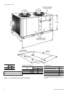
1. Have sufficient clearances been provided?
2. Has allforeign matter beenremoved from theinterior of the
unit (tools, construction or shipping materials, etc.)?
3. Have the outdoor fans been rotated manually to check for
free rotation?
4. Are all wiring connections tight?
5. Does the available power supply agree with the nameplate
data on the unit?
6. Have the fuses, disconnect switch and power wire been
sized properly?
7. Are all compressor hold-down nuts properly secured?
8. Are any refrigerant lines touching each other or any sheet
metal surface? Rubbing due to vibration could cause a re-
frigerant leak.
9. Are there any visible signs of a refrigerant leak, such as oil
residue?
10. Is any electrical wire laying against a hot refrigerant line?
Keep in mind that this unit has a reverse cycle and that dif-
ferent lines will be hot during the “HEAT” and “COOL” cy-
cles. Only two lines will remain cool for all cycles - the line
between the compressor and the accumulator and the line
between the accumulator and the reversing valve.
INITIAL START-UP
1. Supply power to the unit through the disconnect switch
prior to starting the compressor.
2. Move the system switch on the room thermostat to the
“COOL” position, and lower its set point to energize both
the compressor and the reversing valve. Cool air will be
supplied to the conditioned space.
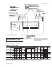
3. Check the compressor amperage. It should notexceed the
RLAratingprinted onthe unitdata plateor inTable 3unless
the ambient temperature is above 105°F.
4.
Move the system switch on the room thermostat to the
“HEAT” position, and increase the set point of the room
thermostat until heating is required. The compressor will
run, but the reversing valve will be de-energized. Warm air
will be supplied to the conditioned space.
5. Check the operation of the indoor unit per
Form 515.41-N4Y.
6. Check the entire system for refrigerant leaks.
7. Check for any abnormal noises and/or vibrations, and make
the necessaryadjustments tocorrect (e.g. fan bladetouching
shroud, refrigerant lines hitting on sheet metal, etc.)
8. After the unit has been operating for several minutes, shut
off the main power supply at the disconnect switch and in
-
spect all factory wiring connectionsand bolted surfaces for
tightness.
SAFETY FEATURES
1. All outdoor fan motors have inherent protection with auto
-
matic reset.
2. Every compressor is internally protected against excessive
currentandtemperature byalinebreakmotorprotector thatis
mounted inside the compressor housing and is connected
between each winding and the common terminal.
This motor protector will interrupt power to the compressor
if any of the following overload conditions occur:
a. primary single phasing
b. locked rotor
c. compressor overload
d. insufficient motor cooling
This typeof motorprotection works evenwith the contactor
welded closed.
3. Every compressor is protected by crankcase heaters to
prevent refrigerant from accumulating in the crankcases of
the compressor during an “OFF” cycle.
4. Outdoor fan motorsand the secondary of thecontrol trans
-
former are grounded.
5. A fusible plug on the top of the suction line accumulator
serves as a high temperature/high pressure relief device.
14 Unitary Products Group
035-16192-001-A-1001
SECURE OWNER'S APPROVAL: When the system is functioning properly, secure the owner's approval. Show him the
location of all disconnect switches and the thermostat. Teach him how to start and stop the unit, how to adjust temperature
settings within the limitations of the system
START-UP
CAUTION:
DO NOT ATTEMPT TO START THE
COMPRESSOR WITHOUT AT LEAST
8 HOURS OF CRANKCASE HEAT
OR COMPRESSOR DAMAGE WILL
OCCUR.
MAINTENANCE
CLEANING
Do not allow dirt to accumulate on the outdoor coil. Clean the
coil with a brush or vacuum cleaner as often as necessary to
assure good system performance and efficient operation. If
the coil is extremely dirty, it may be necessary to use an in
-
dustrial grade detergent and a hose to clean the fin surface.
LUBRICATION
The outdoor fan motors are equipped with factory lubricated
and sealed ball bearings. They do not require any mainte
-
nance.
REPLACEMENT PARTS
Contact your local UPG Distribution Center for replacement
compressors, fan motors, controls, etc.
NOTICE TO OWNER
If a lockout occurs, check the indoor filters and the outdoor coil
before calling a serviceman. If the filters are dirty, clean or re
-
placethem. Ifthereis anaccumulation ofsnow,leavesor debris
blocking the outdoor air coil, remove the blockage. Reset the
thermostat and wait 5 minutes. If the unit doesn't start, call a
serviceman.