


CAUTION: LENGTH OF FORKS MUST BE A MINIMUM OF
54" (when lifting from the compressor end of the
unit) anda MINIMUMOF 42"(when liftingfrom the
front or rear of the unit).
Remove the nesting brackets from the four corners on top of
the unit. All screws that are removed to take these brackets off
must be replaced on the unit.
CLEARANCES
All units require certain minimum clearances for proper opera
-
tion and service. Refer to Figure 4 for these clearances.
WARNING: Do not permit overhanging structures or shrubs
to obstruct air discharge.
Additional height may be required for snow clearance if winter
operation is expected.
COMPRESSOR CRANKCASE HEATER
The compressor is equipped with a crankcase heater to pre
-
vent refrigerant from mixing with crankcase oil during the
“OFF” cycle. The heaters will be energized when the com
-
pressor is not running providing the unit disconnect switch is
closed.
CAUTION: Do not attempt to start the compressor without at
least eight hoursof crankcase heat or compressor
damage will occur.
Ifa unithasjust beeninstalledorthe unitdisconnectswitchhas
beenopen fora longperiod oftime, movethe systemswitch on
the room thermostat to the “OFF” position before closing the
unit disconnect switch. Eight hours of crankcase heat are re
-
quired to drive the liquid refrigerant out of the compressor bef
-
ore the compressor can be started.
POWER AND CONTROL WIRING
Install electrical wiring in accordance with the latest National
Electrical Code (NFPA Standard No. 70) and/or local regula-
tions. The unit should be grounded in accordance with these
codes.
POWER WIRING
Check the voltage of the power supply against the data on
the unit nameplate. Check the size of the power wire, the
disconnect switch and the fuses against the data in Table 3.
NOTE: Copper conductors mustbe installed between the dis
-
connect switch and the unit.
Refer to Figure 4 for the location of the power wire access
opening through the front of the unit. This opening will re
-
quire a field-supplied conduit fitting.
The field-supplied disconnect switch must be suitable for an
outdoor location. Although it should be installed near the unit,
do NOT
secure it to the unit cabinet.
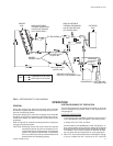
Refer to Figure 3 for typical field wiring.
CONTROL WIRING
Refer to Figure 4 for the location of the control wire access
opening through the front of the unit.
Route the necessary low voltage control wires from terminal
block TB2 of the unit control box through this access open
-
ing to the indoor unit and to the room thermostat. Refer to
Figure 3 for typical field wiring.
The room thermostat should be mounted about 5 feet above
the floor and located where it will be exposed to normal room
air circulation. Do not locate it on an outside wall, near a
supply air grille, or where it may be affected by sunlight
4 Unitary Products Group
035-16192-001-A-1001
O
O
O
O
O
O
O
O
O
O
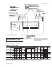
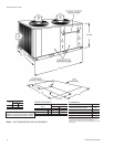
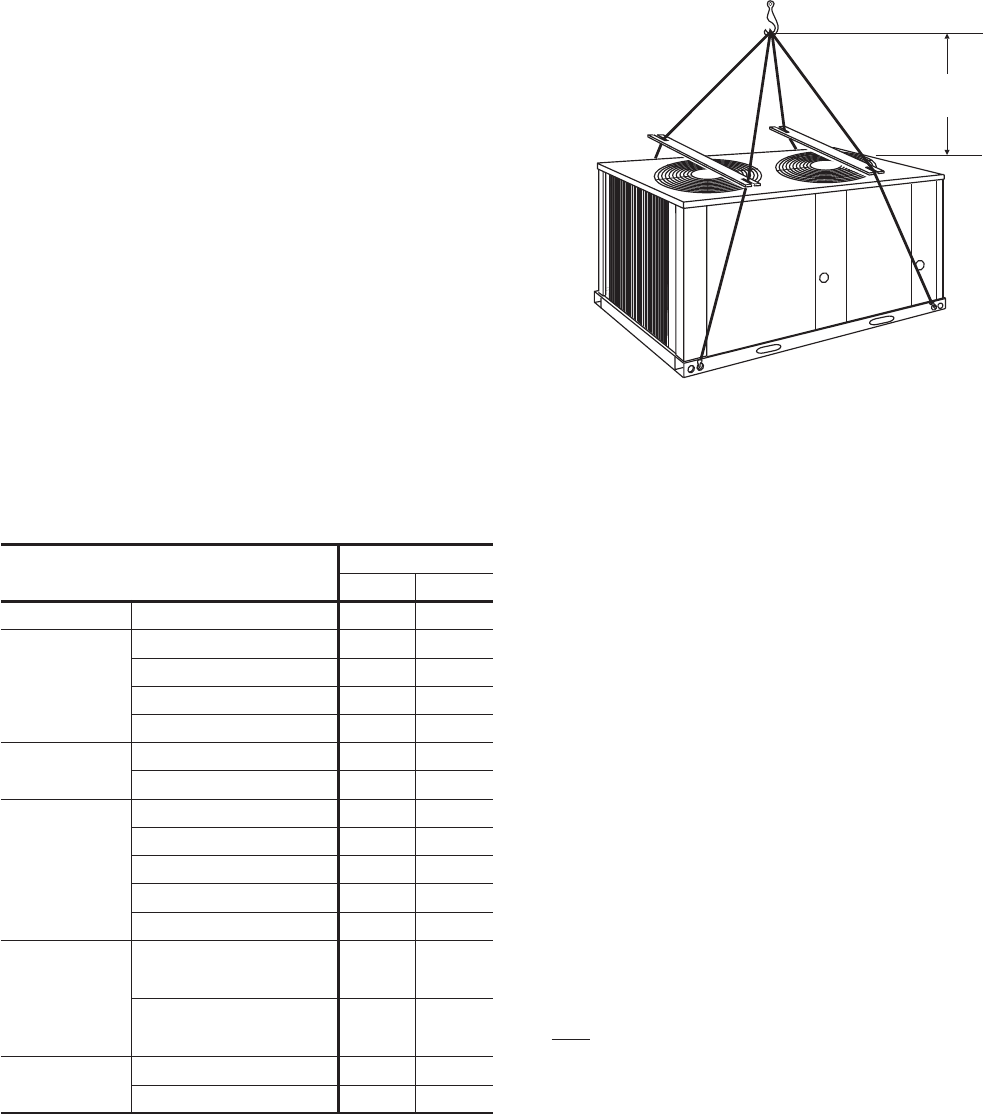
FIG. 2 - TYPICAL RIGGING
5 ft.
MIN
DESCRIPTION
UNIT MODEL
EFB180 EFB240
Compressor
1
Rating - (Qty) Tons (2) 7-1/2 (2) 10
Fans
Quantity 2 2
Diameter - inches 24 26
Blades/Pitch (°) 3/32 3/36
Nominal CFM 10862 11395
Fan Motors
2
HP 1 1
RPM 1100 1100
Rows Deep X Rows High 2 X 40 2 X 40
Finned Length - inches 130 130
Face Area - square feet 36.11 36.11
Tube(Copper) OD - inches 3/8 3/8
Fins (Aluminum) per inch 18 20
Holding Charge
(Sys 1 / Sys 2)
3
1-0/1-0 1-0/1-0
Operating Charge
(Sys 1 / Sys 2)
4
16-8/17-8 19-0/19-0
Shipping 970 1020
Operating 980 1040
1
These compressors are fully hermetic.
2
The ball bearing, 48 frame, single phase condenser fan motor have internal
protection and are directly connected to the condenser fins. Motor rotation is
counterclockwise when viewing the lead end, which is opposite the shaft end.
3
The amount of charge in the unit as shipped from the factory.
4
Totaloperatingchargeforthecondensingunit,matchingindoorunit,and25feet
of interconnecting pipe.
TABLE 2 - PHYSICAL DATA