


360101-XTG-B-0508
Johnson Controls Unitary Products 21
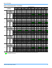
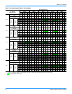
MECHANICAL SPECIFICATIONS
GENERAL DESCRIPTION
Units shall be factory-assembled, single packaged, Electric
Cooling units, designed for outdoor mounted installation. They
shall have built in, equal size, field convertible duct connections
for down discharge supply/return or horizontal discharge
supply/return.
The units shall be factory wired, piped, charged with R-22
refrigerant and factory tested prior to shipment. All unit wiring
shall be both numbered and color coded.
All units shall be manufactured in a facility certified to ISO 9001
standards, and the cooling performance shall be tested in
accordance with ARI test procedures. Units shall be certified to
UL 1995/CAN/CSA C22.2 No. 236 standards.
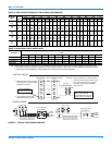
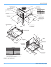
UNIT CABINET
1. Unit cabinet shall be constructed of galvanized steel, with
exterior surfaces coated with a non-chalking, powdered
paint finish, certified at 1000 hours salt spray test per
ASTMB117 standards.
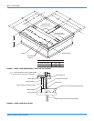
2. The unit top shall be a single piece “Water Shed” design,
with drip edges and no-seam corners to provide optimum
water integrity
3. Unit shall have a rigidly mounted condenser coil guard to
provide protection from objects and personnel after
installation.
4. Indoor blower section shall be insulated with up to 3/4”
thick, aluminum, foil faced insulation, fastened to prevent
insulation from entering the air stream.
5. Cabinet panels shall be “large” size, easily removable for
servicing and maintenance, with built-in lift handles.
6. Unit shall be built on a formed, “Super-Structure” design
base pan, with embossments at critical points to add
strength, rigidity and aid in minimizing sound.
7. Full perimeter base rails shall be provided to assure
reliable transit of equipment, overhead rigging, fork truck
access and proper sealing on roof curb applications. Base
rails shall be removable, when required, to lower unit
height.
8. Filters shall be furnished and be accessible through a
removable access door, sealed air tight. (Single phase
models - accessory kit available. Three phase models -
standard from factory.)
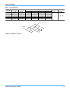
9. Units vertical discharge and return duct configuration shall
be designed to fit between standard 24” O.C. beams
without modification to building structure, duct work and
base unit.
10. Condensate pan shall be internally sloped and conform to
ASHRAE 62-89 self-draining standards, with 3/4” NPTI
copper, ridged mount connection.
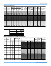
INDOOR (EVAPORATOR) FAN ASSEMBLY
1. Fan shall be direct drive, multi-speed design. Job site
selected (BHP) brake horse power shall not exceed the
motors nameplate horse power rating.
2. Fan wheel shall be double-inlet type with forward-curved
blades, dynamically balanced to operate smoothly
throughout the entire range of operation. Airflow design
shall be constant air volume.
3. Bearings shall be sealed and permanently lubricated for
longer life and no maintenance.
4. Fan assembly shall be “Slip Track” (slide-out) design for
easy removal and cleaning.
OUTDOOR (CONDENSER) FAN ASSEMBLY
1. The outdoor fan shall be of the direct-driven propeller type,
discharge air vertically, have aluminum blades riveted to
corrosion resistant steel spider bracket and shall be
statically balanced for smooth operation.
2. The outdoor fan motor shall be totally enclosed with
permanently lubricated bearings and internally protected
against overload conditions.
REFRIGERANT COMPONENTS
1. Compressors:
a. Shall be fully hermetic reciprocating type, direct drive,
internally protected with internal high-pressure relief and
over temperature protection. The hermetic motor shall be
suction gas cooled and have a voltage range of + or -
10% of the unit nameplate voltage.
b Shall have internal isolation and sound muffling to
minimize vibration and noise, and be externally isolated
on a dedicated, independent mounting.
2. Coils:
a. Evaporator and condenser coils shall have aluminum
plate fins mechanically bonded to seamless internally-
enhanced copper tubes with all joints brazed.
b Evaporator and Condenser coils shall be of the direct
expansion, draw-thru design.
3. Refrigerant Circuit and Refrigerant Safety Components
shall include:
a. Independent fixed-orifice expansion devices.
b. Filter/strainer to eliminate any foreign matter.
c. Accessible service gauge connections on both suction
and discharge lines to charge, evacuate, and measure
refrigerant pressure during any necessary servicing or
troubleshooting, without losing charge and without
disrupting condenser or evaporator air flow.
d The refrigeration system shall provide at least 10° F of
liquid sub-cooling at design conditions.
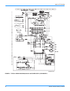
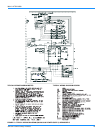
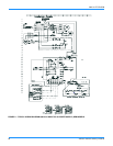
4. Unit Controls: a. Unit shall contain a large, low voltage Terminal Board for
easy connection of field low voltage wiring.