


360101-XTG-B-0508
Johnson Controls Unitary Products 11
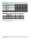
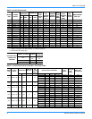
Note:1. Deduct these resistance values from the available external static pressure shown in the respective Blower Performance Table.
2. The pressure thru the economizer is greater for 100% outdoor air then for 100% return air. If the resistance of the return air duct
system is less then 0.25 IWG, the unit will deliver less CFM during full economizer operation.
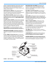
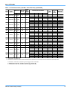
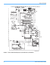
FIGURE 2 - TYPICAL FIELD WIRING DIAGRAM
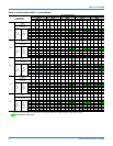
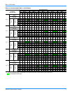
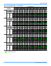
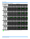
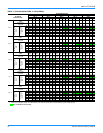
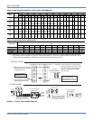
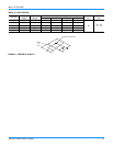
TABLE 8: SIDE AND BOTTOM SUPPLY AIR BLOWER PERFORMANCE
Model No.
DEB
Blower
Speed
Setting
External Static Pressure (Inches Water Gauge)
0.1 0.2 0.3 0.4 0.5 0.6 0.7 0.8 0.9 1.0 1.1
CFM W CFM W CFM W CFM W CFM W CFM W CFM W CFM W CFM W CFM W CFM W
030
(2.5)
High --------11715041080486990468888456786444----
Medium 1080 351 1021 341 961 331 902 321 841 305 781 290 - - - - - -----
Low 810261765240------------------
036
(3.0)
High - - - - 1440 605 1361 581 1273 555 1185 530 1097 504 1004 480 912 456 - - - -
Medium 1465 531 1395 512 1325 492 1255 473 1167 446 1079 419 992 392 - - - -----
Low 1316 473 1260 455 1204 438 1148 420 1069 396 990 372 911 348 - - - -----
042
(3.5)
High - - - - 1728 725 1633 697 1527 666 1422 635 1317 605 1205 576 1094 547 - - - -
Medium - - 1674 614 1590 590 1506 567 1400 535 1295 502 1190 470 1063 428 - -----
Low 1579 567 1512 546 1444 525 1377 504 1282 476 1188 447 1093 418 - - - -----
048
(4.0)
High - - 1985 870 1939 850 1897 830 1813 800 1728 770 1644 740 1559 707 1474 673 1389 640 - -
Medium 1694 690 1662 673 1629 657 1597 640 1542 623 1486 607 1431 590 1336 563 1240 537 - - - -
Low 1385 520 1349 510 1312 500 1276 490 1235 480 - - - - --------
060
(5.0)
High - - - - 2450 1213 2366 1165 2282 1117 2198 1068 2114 1020 1989 993 1864 967 1739 940 - -
Medium 2339 1170 2275 1118 2211 1067 2147 1015 2083 963 2019 912 1955 860 1854 824 1753 788 1652 752 - -
Low 1929 940 1877 903 1824 867 1772 830 1720 793 1667 757 1615 720 1586 706 1557 691 1528 677 - -
TABLE 9: ADDITIONAL STATIC RESISTANCE
Description
Resistance, IWG
CFM
500 600 700 800 900 1,000 1,100 1,200 1,300 1,400 1,500 1,600
Wet Evaporator Coil .01 .01 .01 .02 .03 .04 .05 .06 .07 .08 .09 .09
Economizer .00 .00 .00 .01 .01 .01 .01 .02 .03 .04 .05 .06
Filter/Frame Kit .01 .02 .02 .02 .02 .02 .03 .03 .03 .03 .04 .05
Electric Heat .02 .03 .03 .03 .04 .04 .05 .06 .07 .08 .09 .10
R
G
W
R
G
C
Y Y
W
C
THERMOSTAT
PROGRAMMABLE
THERMOSTAT ONLY
UNIT TERMINAL STRIP
24 VOLT
TRANSFORMER
NOTE:
HEAT ANTICIPATOR
SHOULD BE SET AT 0.25
AMPS FOR ALL MODELS
Minimum wire size of 18 AWG
wire should be used for all field
installed 24 volt wire.
** =
Only required on units with
supplemental electric heat.
* =
**
*
CAUTION: Label all wires prior to disconnection
when servicing controls. Wiring errors
can cause improper and dangerous
operation. Verify proper operation
after servicing.
CONTROL WIRING
POWER WIRING
CONTACTOR
FIELD SUPPLIED
DISCONNECT
THREE
PHASE
POWER
SUPPLY
GROUND
LUG
CONTACTOR
FIELD SUPPLIED
DISCONNECT
SINGLE
PHASE
POWER
SUPPLY
GROUND
LUG
REFER TO ELECTRICAL DATA
TABLES TO SIZE THE DISCON-
NECT SWITCH, WIRING AND
OVERCURRENT PROTECTION.
REFER TO ELECTRICAL DATA
TABLES TO SIZE THE DISCON-
NECT SWITCH, WIRING AND
OVERCURRENT PROTECTION.