


255027-YTG-B-0507
Unitary Products Group 33
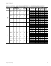
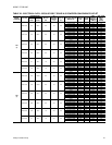
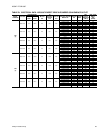
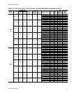
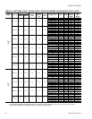
TABLE 25: PHYSICAL DATA
MODELS
BP
036 048 060 072
EVAPORATOR
BLOWER
Centrifugal Blower (Belt Drive) (Dia. x Wd. in.) 12 x 10 12 x 10 12 x 10 12 x 11
Centrifugal Blower (Direct Drive) (Dia. x Wd. in.) 12 x 10 12 x 10 12 x 10 12 x 10
Fan Motor HP (Direct Drive) 3/4 1 1 1
Fan Motor HP (Belt Drive) 1 1/2 1 1/2 1 1/2 1 1/2
EVAPORATOR
COIL
Rows Deep 3 4 4 4
Fins Per Inch 13 13 13 13
Face Area (Sq. Ft.) 5.1 5.1 5.1 5.1
CONDENSER
FANS
Propeller Dia. (in.) 24 24 24 24
Fan Motor Hp 1/2 1/2 1/2 1/2
Nom. CFM 4200 4200 4200 4200
CONDENSER
COILS
Rows Deep 2 2 2 2
Fins Per Inch 18 18 18 18
Face Area (Sq. Ft.) 17.1 17.1 17.1 17.1
COMPRESSOR
Quantity 1111
Type Reciprocal Reciprocal Scroll Scroll
AIR
FILTERS
Quantity Per Unit (15” X 20” X 1” or 2“) 2 2 2 2
Quantity Per Unit (14” X 25” X 1” or 2“) 1 1 1 1
Total Face Area (sq. ft.) 6.3 6.3 6.3 6.3
CHARGE
Refrigerant 22 (lbs./oz.) 11/12 12/8 13/4 12/0
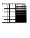
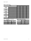
TABLE 26: ELECTRIC HEAT CORRECTION
FACTORS
NOMINAL VOLTAGE VOLTAGE
kW CAP. MULTI-
PLIER
208
208 0.75
240
230 0.92
480
460 0.92
600
575 0.92
TABLE 27: VOLTAGE LIMITATIONS
1
1. Utilization Range “A” in accordance with ARI Standard
110.
POWER SUPPLY
VOLTAGE
MIN. MAX.
208/230-1-60
187 253
208/230-3-60
187 253
460-3-60
414 506
575-3-60
518 506