


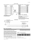

Refer to the Typical Field Wiring Figure and to the appropriate
unit wiring diagram for control circuit and power wiring
information.
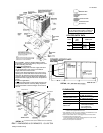
OPTIONAL ELECTRIC HEATERS
The factory installed heaters are wired for single point power
supply. Power supply need only be brought into the single point
terminal block and thermostat wiring to the low voltage terminal
strip located in the upper portion of the unit control box.
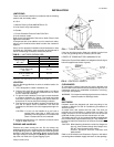
These ETL and CGA approved heaters are located within the
central compartment of the unit with the heater elements
extending into the supply air chamber. Refer to the Dimensions
and Clearances Figure for access panel location.
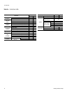
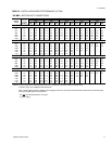
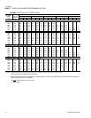
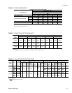
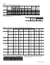
Fuses are supplied, where required, by the factory. Some KW sizes
require fuses and others do not. Refer to the Electric Heat Application
table for minimum CFM limitations and to the Electrical Data table for
electrical data.
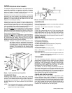
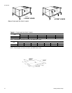
OPTIONAL ECONOMIZER/MOTORIZED DAMPER
RAIN HOOD
The instruction for the optional economizer/motorized damper
rain hood can be found in form 44-320-2. Use these instructions
when field assembling an economizer rain hood onto a unit.
The outdoor and return air dampers, the damper actuator, the
damper linkage, the outdoor and return air divider baffles, and
all the control sensors are factory mounted as part of the
"Factory installed" economizer option.
ENTHALPY SET POINT ADJUSTMENT
Remove the economizer access panel from the unit to check
the following adjustments. Loosen but do not remove the two
panel latches.
CAUTION: Extreme care must be exercised in turning both
the setpoint and minimum position adjusting
screws to prevent twisting them off.
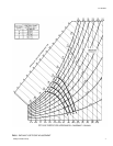
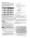
1. The enthalpy set point may now be set by selecting the
desired setpoint shown in the Adjusting Enthalpy Setpoint
Figure. Adjust as follows:
•
For a single enthalpy operation, carefully turn the set
point adjusting screw to the “A”, “B”, “C” or “D” setting
corresponding to the lettered curve.
•
For a dual enthalpy operation, carefully turn the set point
adjusting screw fully clockwise past the “D” setting.
2. To check that the damper blades move smoothly without
binding, carefully turn the minimum position adjusting
screw fully clockwise and then energize and de-energize
terminals “R” to “G”. With terminals “R” to “G” energized,
turn the minimum position screw counterclockwise until the
desired minimum position has been attained.
3. Replace the economizer access panel. Reposition the two
latches horizontally and retighten the screws.
POWER EXHAUST/BAROMETRIC RELIEF DAMPER
AND RAIN HOOD OPTION
The instructions for the power exhaust/barometric relief
damper and rain hood can be found in form 44-320-10. The
exhaust fan, all supporting brackets, angles, and the wiring are
factory installed as part of the power exhaust option.
All of the components, including the dampers, hardware, and
mounting instructions are shipped in a single package external
from the unit. The hood must be field assembled and installed.
Power exhaust is not available as a field installed option.
NOMINAL
HEATER SIZE
(KW)
VOLTAGE
3 PHASE,
60 HZ
MINIMUM CFM
(UNIT SIZE)
15 TON 20 TON
18 208/230,460,575 4500 6000
36 208/230,460,575 4500 6000
54
208/230 5000
6000
460, 575 4500
72
208/230 5000
6000
460, 575 4500
TABLE 3
- ELECTRIC HEAT APPLICATION DATA
511.06-N3Y
6 Unitary Products Group