


The internal wiring harness furnished with this unit is an integral
part of a ETL and CGA design certified unit. Field alteration to
comply with electrical codes should not be required.
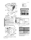
A fused disconnect switch should be field provided for the unit.
The switch must be separate from all other circuits. Wire entry
at knockout openings require conduit fittings to comply with
CEC (in Canada), NEC (in U.S.A.) and/or local codes. Refer to
the Dimensions and Clearances Figure for installation location.
If any of the wire supplied with the unit must be replaced,
replacement wire must be of the type shown on the wiring
diagram and the same minimum gauge as the replaced wire.
Electrical line must be sized properly to carry the load. Each
unit must be wired with a separate branch circuit fed directly
from the meter panel and properly fused.
CAUTION: When connecting electrical power and control
wiring to the unit, waterproof type connectors
MUST BE USED so that water or moisture cannot
be drawn into the unit during normal operation. The
above waterproofing conditions will also apply
when installing a field-supplied disconnect switch.
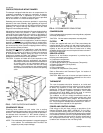
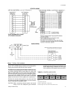
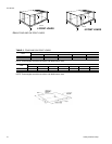
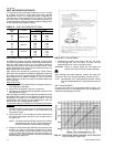
FIG. 5
- TYPICAL FIELD WIRING
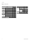
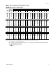
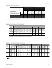
Wire Size
1
AWG. Gauge
22 20 19 18 16
40 120 150 190 305
Maximum Wire Length
2
Feet
Notes:
1. Solid, Class II copper wire
2. Based on a voltage drop of 1.2 volts per wire.
3. Total wire length is from unit to room thermostat, and back to unit
TABLE 2 -
CONTROL WIRE SIZES
511.06-N3Y
Unitary Products Group 5