


General ................................................................................ 1
Inspection............................................................................. 1
Reference............................................................................. 1
Approvals ............................................................................. 1
Nomenclature....................................................................... 2
INSTALLATION
Limitations............................................................................ 3
Location ............................................................................... 3
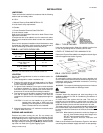
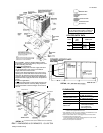
Rigging and Handling .......................................................... 3
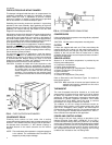
Clearances........................................................................... 3
Ductwork .............................................................................. 3
Fixed Outdoor Air Intake Damper ........................................ 4
Condensate Drain................................................................ 4
Compressors........................................................................ 4
Filters ................................................................................... 4
Service Access .................................................................... 4
Thermostat........................................................................... 4
Power and Control Wiring .................................................... 4
Optional Electric Heaters..................................................... 5
Optional Economizer/Mot. Damper Rain Hood ................... 5
Optional Power Exhaust Rain Hood .................................... 7
OPERATION
Cooling System.................................................................. 15
Preliminary Operation Cooling........................................... 15
Cooling Sequence of Operation......................................... 15
Heating Sequence of Operation ........................................ 15
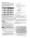
Heat Anticipator Setpoints ................................................. 16
Checking Supply Air CFM.................................................. 16
Defrost Sequence of Operation ......................................... 17
Secure Owner’s Approval .................................................. 18
MAINTENANCE
Normal Maintenance ......................................................... 18
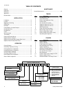
TABLES
No. Description Page
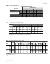
1 Unit Application Data .................................. 3
2 Control Wire Sizes ...................................... 5
3 Electric Heat Application Data.................... 5
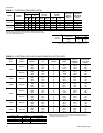
4 Physical Data.............................................. 8
5 Four and Six Point Loads............................ 10
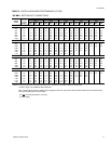
6 Supply Air Blower Perf. 15 Ton.................... 12
7 Supply Air Blower Perf. 20 Ton.................... 12
8 Static Resistances ...................................... 13
9 Power Exhaust Performance ...................... 13
10 Blower Motor and Drive Data...................... 13
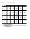
11 Electrical Data (Basic Units)....................... 14
12 Electrical Data (Units w/Elec. Heat)............ 14
13 Heat Anticipator Setpoints .......................... 16
FIGURES
No. Description Page
1 Typical Rigging............................................ 3
2 Center of Gravity......................................... 3
3 Fixed Outdoor Air Damper.......................... 4
4 Recommended Drain Piping....................... 4
5 Typical Field Wiring ..................................... 5
6 Adjusting Enthalpy Setpoint........................ 7
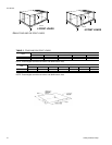
7 Dimensions and Clearances....................... 9
8 Four and Six Point Loads............................ 10
9 Belt Adjustment........................................... 16
10 Pressure Drop versus Supply Air CFM ...... 16
11 Defrost Initiation Times ............................... 17
12 Ambient Modified Time/Temp. Control........ 18
TABLE OF CONTENTS
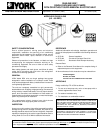
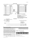
B 1 C H E C1E
PRODUCT NOMENCLATURE
PRODUCT GENERATION
1 = 1st Generation
PRODUCT CATEGORY
B = Single Package Heat Pump
(Air Cooled)
PRODUCT IDENTIFIER
CH = Heat Pump
VOLTAGE CODE
25 = 208/230-3-60
46 = 460-3-60
58 = 575-3-60
NOMINAL HEATING
CAPACITY
180 = 15 Tons
240 = 20 Tons
FACTORY INSTALLED
OPTION CODE
EC = Sing. Input Economizer
DK = Diff. Input Economizer
FD = Sing. Input Economizer
w/Power Exhaust
CF = Diff. Input Economizer
w/Power Exhaust
BG = Motor Outdoor Air
Damper
0 881 0 2 5
FACTORY INSTALLED
HEAT
A = No Heat
E = Electric
NOMINAL COOLING
CAPACITY
018 = 18 KW
036 = 36 KW
054 = 54 KW
072 = 72 KW
511.06-N3Y
2 Unitary Products Group