


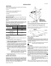
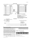
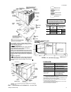
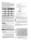

FIXED OUTDOOR AIR INTAKE DAMPER
This damper is shipped inside the return air compartment. It is
completely assembled and ready for installation. A damper
baffle inside the hood is adjustable to provide variable
amounts of outdoor air intake on units that are not provided
with an economizer or a motorized damper option.
Gasketing and mounting screws are provided in a parts bag
attached to the hood assembly. Apply gasketing to the three
flange surfaces on the hood prior to installing the hood. Extend
gasketing 1/4" beyond the top and bottom of the two side
flanges to insure adequate sealing.
Adjusting the damper to the desired air flow may be done before
mounting the hood into position or (after installation) by
removing the front hood panel or the screen on the bottom of
the hood. Damper baffle in position 1 will allow approximately
10% recirculated air flow, position 2 approximately 15% and, to
allow approximately 25%, remove the damper baffle.
On units with
bottom return air applications, install the damper
assembly over the opening in the side return air access panel.
Remove and discard the opening cover and the covering over
the hood mounting holes (used for shipping) before installing.
Secure with the screws provided.
On units with side return air applications, install the damper
assembly on the return air ductwork as close to the unit as
possible. Cut an opening 16" high by 18" wide in the ductwork
to accommodate the damper. Using the holes in the hood
flanges as a template, drill 9/64" dia. (#26 drill) holes into the
ductwork and secure with the screws provided.
CAUTION: If outdoor air intake will not be required on units
with bottom return air applications, the damper
assembly should still be mounted on the side return
air access panel, per the instructions above, to
insure moisture is not drawn into the unit during
operation. The covering over the mounting holes
only need be removed. Do not remove the opening
cover.
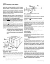
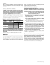
CONDENSATE DRAIN
Plumbing must conform to local codes. Use a sealing
compound on male pipe threads. Install a condensate drain line
from the 1" NPT female connection on the unit to an open drain.
An alternate drain connection (1" NPT female coupling) is
provided inboard on the same centerline as the exterior
location.
NOTE: The condensate drain operates in a negative pressure
in the cabinet. The condensate drain line MUST be
trapped to provide proper drainage.
COMPRESSORS
Units are shipped with compressor mountings factory-adjusted
and ready for operation.
CAUTION: Do Not loosen compressor mounting bolts.
FILTERS
2" filters are supplied with each unit. Filters must always be
installed ahead of the indoor coil and must be kept clean or
replaced with same size and type. Dirty filters will reduce the
capacity of the unit and will result in frosted coils or safety
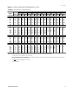
shutdown. Minimum filter area and required sizes are shown in
the Physical Data table.
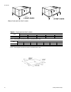
SERVICE ACCESS
Access to all serviceable components is provided by the
following removable panels:
•
Compressor compartment
•
Electric Heat compartment
•
Side Supply & Return Air compartments (Two panels)
•
Blower compartment (Three panels)
•
Main control box
•
Filter compartment
•
Outdoor Air compartment (Two panels)
Refer to Dimensions and Clearnaces Figure for location of
these access panels.
CAUTION: Make sure that all screws and panel latches are
replaced and properly positioned on the unit to
maintain an air-tight seal.
THERMOSTAT
The room thermostat should be located on an inside wall
approximately 56" above the floor where it will not be subject
to drafts, sun exposure or heat from electrical fixtures or
appliances. Follow manufacturer’s instructions enclosed with
thermostat for general installation procedure. Color coded
insulated wires (#18 AWG) should be used to connect
thermostat to unit. Eight conductors are required.
The subbase on the low voltage thermostat includes an
"Emergency Heat" position on the system switch and a pilot
light. In the "Emergency Heat" position, the thermostat will
provide electric resistance heat only. The compressors will not
run. The pilot light will indicate that the switch is on "EM HT".
Nine conductors are required for this application.
POWER AND CONTROL WIRING
Field wiring to the unit must conform to provisions of the
National Electrical Code, ANSI / NFPA No. 70 (in U.S.A.),
current Canadian Electric Code (CEC) CSA C22.1 (in Canada)
and/or local ordinances. The unit must be electrically grounded
in accordance with NEC and CEC (as specified above) and/or
local codes. Voltage tolerances which must be maintained at
the compressor terminals during starting and running
conditions are indicated on the unit Rating Plate.
FIG. 3
- FIXED OUTDOOR AIR DAMPER
FIG. 4 -
RECOMMENDED DRAIN PIPING
511.06-N3Y
4 Unitary Products Group