


LIMITATIONS
These units must be installed in accordance with the following
national and local safety codes:
In U.S.A.:
1. National Electrical Code ANSI/NFPA No. 70.
2. Local electric utility requirements.
In Canada:
1. Current Canadian Electrical Code CSA C22.1.
2. Local electrical codes.
Refer to the Unit Application Data and to thefor Electric Heat
Application Data table.
If components are to be added to a unit to meet local codes,
they are to be installed at the dealer’s and/or the customer’s
expense.
Size of unit for proposed installation should be based on heat
loss/heat gain calculation made according to the methods of
the Air Conditioning Contractors of America (ACCA).
LOCATION
Use the following guidelines to select a suitable location for
these units.
1. Unit is designed for outdoor installation only.
2. Outdoor coils must have an unlimited supply of air. Where
a choice of location is possible, position the unit on either
north or east side of building.
3. For ground level installation, use a level concrete slab with
a minimum thickness of 4 inches. The length and width
should be at least 6 inches greater than the unit base rail
dimensions. Do not tie slab to the building foundation.
4. Roof structures must be able to support the weight of the
unit and its options and/or accessories. Unit must be
installed on a solid level roof curb or appropriate angle iron
frame.
CAUTION: If a unit is to be installed on a roof curb or
special frame other than a YORK roof curb,
gasketing must be applied to all surfaces that
come in contact with the unit underside.
5. Maintain level tolerance to 1/2" maximum across the entire
length or width of the unit.
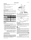
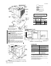
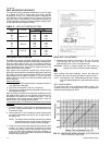
RIGGING AND HANDLING
Exercise care when moving the unit. Do not remove any
packaging until the unit is near the place of installation. Rig the
unit by attaching chain or cable slings to the round lifting holes
provided in the base rails. Spreaders, whose length exceeds
the larger dimension across the unit,
MUST
be used across the
top of the unit. Refer to the Typical Rigging Figure.
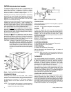
Units may also be moved or lifted with a forklift, from the front
or rear only, providing that an accessory skid is used.
LENGTH OF FORKS MUST BE A MINIMUM OF 90".
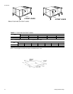
Refer to the Physical Data tablefor unit weights and to the figure
below for approximate center of gravity.
CLEARANCES
All units require certain clearances for proper operation and
service. Refer to the Dimensions and Clearances Figure for the
clearances required for combustible construction, servicing,
and proper unit operation.
WARNING: Do not permit overhanging structures or shrubs to
obstruct outdoor air discharge outlet.
DUCTWORK
Ductwork should be designed and sized according to the
methods in Manual Q of the Air Conditioning Contractors of
America (ACCA).
A closed return duct system shall be used. This shall not
preclude use of economizers or outdoor fresh air intake. The
supply and return air duct connections at the unit should be
made with flexible joints to minimize transmission of noise.
The supply and return air duct systems should be designed for
the CFM and static requirements of the job. They should
NOT
be sized to match the dimensions of the duct connections on
the unit.
CAUTION: When fastening ductwork to side duct flanges on
the unit, insert screws through duct flanges only.
DO NOT insert screws through casing.
Outdoor ductwork must be insulated and
waterproofed.
Refer to the Dimensions and Clearances Figure for information
concerning side and bottom supply and return air duct openings.
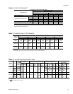
INSTALLATION
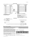
Model Size 15 TON 20 TON
Voltage Variation,
Min. / Max.
1
208/230-3-60 187 / 253
460-3-60 414 / 506
575-3-60 518 / 630
Supply Air CFM, Min. / Max. 4500
2
/ 7200 6000 / 9400
Wet Bulb Temperature (
°
F)
of Air on Indoor Coil
Min. / Max.
57 / 72
Dry Bulb Temperature (
°
F)
of Air on Outdoor Coil
Min. / Max.
45 / 120
1
Rated in accordance with ARI Standard 110, utilization range "A".
2
5,000 CFM on 15 ton models with either a 54 or 72 KW heater at 208/230 volts.
TABLE 1
- UNIT APPLICATION DATA
FIG. 1
- TYPICAL RIGGING
OUTDOOR
COIL END
FIG. 2
- CENTER OF GRAVITY
511.06-N3Y
Unitary Products Group 3