


036-21103-003 Rev. A (0403)
2 Unitary Products Group
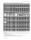
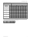
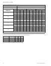
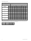
PHYSICAL AND ELECTRICAL DATA - 1 & 3 Phase
MODEL
H1RA018S78 H1RA024S78 H1RA030S78 H1RA036S78 H1RA036S50 H1RA048S50 H1RA060S50
Unit Supply Voltage 230 – 1 – 50 380/415 – 3 – 50
Normal Voltage Range
1
1. Rated in accordance with ARI Standard 110, utilization range “A”.
207 to 253 342 to 455
Minimum Circuit Ampacity 9.8 14.6 20.4 20.8 7.3 10.8 13.3
Max. Qvercurrent Device Amps
2
2. Dual element fuses or HACR circuit breaker.
15 25 35 35 15 15 20
Compressor Type Recip Recip Recip Recip Recip Recip Recip
Compressor Amps
Rated Load 7.4 11.3 15.2 15.5 5.2 7.2 9.2
Locked Rotor53659082395379
Crankcase Heater No No No No No No No
Fan Motor Amps Rated Load .5 .5 1.8 1.8 .8 1.8 1.8
Fan Diameter Inches 18 18 18 18 18 22 22
Fan Motor
Rated HP 1/12 1/12 1/4 1/4 1/4 1/3 1/3
Nominal RPM 970 970 900 900 1,100 1,075 1,075
Nominal CFM 1,650 1,650 2,350 2,350 2,250 3,200 3,300
Coil
Face Area Sq. Ft. 8.00 8.00 9.15 9.15 9.15 15.72 23.58
Rows Deep 1111111
Fin / Inches 14 14 16 16 18 18 18
Liquid Line OD 3/8 3/8 3/8 3/8 3/8 3/8 3/8
Vapor Line OD 3/4 3/4 3/4 3/4 3/4 7/8 7/8
Unit Charge (Lbs. - Oz.)
3
3. The Unit Charge is correct for the outdoor unit, matched indoor coil and 15 feet of refrigerant tubing. For tubing lengths other than
15 feet, refer to publication 035-15893-60*
3 - 13 3 - 14 3 - 15 4 - 11 4 - 11 7 - 10 9 - 12
Charge Per Foot, Oz. 0.66 0.66 0.68 0.68 0.68 0.70 0.70
Operating Weight Lbs. 118 123 135 137 137 206 228
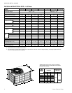
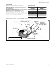
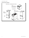
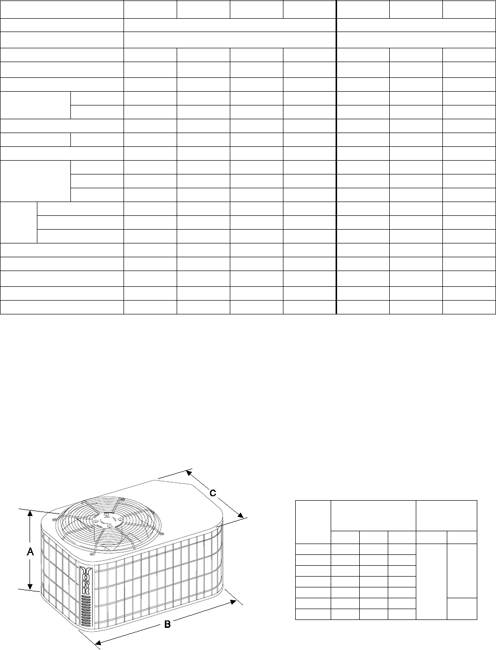
UNIT
MODEL
H1RA
DIMENSIONS
(INCHES)
REFRIGERANT
CONNECTION
LINE SIZE
A
1
1. Including fan guard
B C Liquid Vapor
018S78 17 35 23
3/8”
3/4”
024S78 17 35 23
030S78 19 35 23
036S78 19 35 23
036S50 19 35 23
048S50 27 37 27
7/8”
060S50 39 37 27
All dimensions are in inches. They are subject to
change without notice. Certified dimensions will be
provided upon request.