


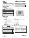

7
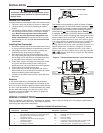
OPERATING YOUR THERMOSTAT
Choose the Fan Setting (Auto or On)
Press the FAN button to Auto or On.
Fan Auto is the most commonly selected setting and runs the
fan only when the heating or cooling system is on.
Fan On runs the fan continuously for increased air circulation
or to allow additional air cleaning.
Choose the System Setting
(Heat, Off, Cool, Auto, Emer)
Press the SYSTEM button to select:
Heat: Thermostat controls only the heating system.
Off: Heating and Cooling systems are off.
Cool: Thermostat controls only the cooling system.
Auto: Auto Changeover is used in areas where both heating
and cooling may be required on the same day. AUTO allows
the thermostat to automatically select heating or cooling
depending on the indoor temperature and the selected heat
and cool temperatures. When using AUTO, be sure to set the
Cooling temperatures more than 1° Fahrenheit higher than
the heating temperature.
Emer: (Heat Pump models) Thermostat controls only backup
heating system.
Manual Operation for Non-Programmable Mode
Press the SYSTEM button to select Heat or Cool and use
the
or buttons to adjust the temperature to your
desired setting. After selecting your desired settings you can
also press the SYSTEM button to select AUTO to allow the
thermostat to automatically change between Heat and Cool.
IMPORTANT!
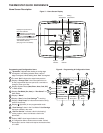
INSTALLER/CONFIGURATION MENU
19) Comfort Alert with Active Protection – Turn this
feature ON to enable active protection. This allows the
thermostat to identify fault codes sent by the Comfort
Alert module when compressor damage is possible and
react to those codes by turning the compressor off. Fault
codes from the Comfort Alert module will flash on the
thermostat. (Refer to Comfort Alert Yellow Alert Codes
in Troubleshooting section.) If a Comfort Alert module is
not connected, or to disable active protection, turn this
feature OFF. If a Comfort Alert module is connected and
this feature is turned OFF, the thermostat will still receive
and flash the fault codes from the Comfort Alert module,
but the active protection will not be enabled to protect the
compressor.
20 & 21) Select Filter Replacement Reminder and Set
Run Time – Select the “Change Filter” reminder On
or OFF. If selected On, press MENU to select the time
period from 25 to 1975 hours in 25 hours increments.
In a typical system, 200 hours (default) of run time is
approximately 30 days. After the selected time of blower
operation, the thermostat will display “Change Filter”
as a reminder to change or clean your air filter. When
“Change Filter” is displayed, press MENU or RUN
SCHED button to clear the display and restart the time to
the next filter change.
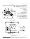
22) Select Reversing Valve Output – The O/B option is
factory set at “O” position. This will accommodate the
majority of heat pump applications, which require the
changeover relay to be energized in COOL. If the
thermostat you are replacing or the heat pump being
installed with this thermostat requires a “B” terminal, to
energize the changeover relay in HEAT, the O/B option
should be set at “B” position.
Second Stage Time Delay
Your thermostat is designed to determine the optimum time
to activate the second stage. Simply raising the temperature
in heating or lowering it in cooling will not always force the
thermostat to bring the second stage on quickly. There is a
time delay from 0-30 minutes depending on the performance
of the first stage of the system.
EXAMPLE: For the last 2 hours the thermostat is set on 70°
and the room temperature is 70° with the equipment using
only the first stage of heat. Since the equipment is keeping
the temperature within 1° of setpoint, the thermostat will
delay second stage for a longer time if you manually raise the
temperature or if the room temperature quickly changes. Once
the second stage comes on, it will come on sooner the next
time there is a difference between the setpoint and the room
temperature. The net effect of the staging program is that when
the first stage is capable of making temperature the second
stage will delay longer. When the thermostat calculates that
first stage cannot make temperature in a reasonable time,
the second stage will come on sooner. This built in function
automatically optimizes the use of additional stages of heat
or cool.
Comfort Alert Codes
The Comfort Alert diagnostics product monitors the air con-
ditioning outdoor systems with single phase Copeland Scroll
compressors. Abnormal system and electrical conditions are
indicated by flashing ALERT codes on the yellow LED on the
Comfort Alert module. The flash codes are transmitted to the
thermostat by the Comfort Alert Thermostat interface module.
The Comfort Alert compatible thermostat displays “Call For
Service” that flashes at the same rate as the yellow LED on
the Comfort Alert module.
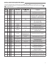
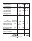
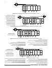
Comfort Alert Yellow Alert Codes
1 Flash Long run time
2 Flashs System pressure trip
3 Flashs Short cycling
4 Flashs Locked rotor
5 Flashs Open circuit
6 Flashs Open start circuit
7 Flashs Open run circuit
8 Flashs Welded Contactor
9 Flashs Low voltage
TROUBLESHOOTING