


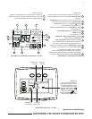

3
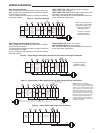
WIRING DIAGRAMS
Heat Pump Connections
If you do not have a heat pump system, refer to figures 4-6.
Refer to equipment manufacturers’ instructions for specific
system wiring information.
You can configure the thermostat for use with the following
heat pump systems.
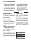
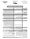
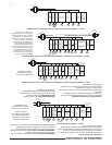
Figure 3 – Heat Pump Systems
HEAT PUMP TYPE 1 (HP 1). Single stage compressor
system; gas or electric backup.
HEAT PUMP TYPE 2 (HP 2). Multi-stage compressor or two
compressor system with gas or electric backup.
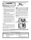
After wiring, see INSTALLER CONFIGURATION section for
proper thermostat configuration.
NOTE: If your system does
not provide an E connection,
jumper W2 to W/E to use
the Auxiliary Heat in the
Emergency Mode.
* Common connection
required for fault or
malfunction indication.
Heat Pump 2
(HP2)
Heat Pump 1
(HP1)
O
Energized in
Cool Mode
B
Energized in
Heat, Off,
Emergency
Mode
2nd
Stage
(Com-
pressor)
No
Output
Heat and
Cool Mode
1st Stage
(Compressor)
Blower/
Circulator
Fan Energized
on Call for
Heat or Cool.
Set Elect/Gas
Option for
Emergency
Mode
Heat Mode
2nd Stage.
Emergency
Mode 2nd
Stage
Heat Mode
3rd Stage.
Emergency
Mode 2nd
Stage
Emergency
Mode
1st Stage
Optional*
24 Volt
(Com-
mon)
Fault Indicator
or System
Malfunction
Switch
24 Volt
(Hot)
Cool
System
Y
W/E
C
L
RC
CLASS II
TRANSFORMER
HOT
24VAC
NEUTRAL
120VAC
24 Volt
(Hot)
Heat
RH
Jumper
Y2
W2
G
Jumper
Comfort Alert II Module
or Similar System
Malfunction Module
O/B
Single Stage and Multi-Stage Connections
Refer to equipment manufacturers’ instructions for specific
system wiring information.
This thermostat is designed to operate a single-transformer
or two-transformer system.
You can configure the thermostat for use with the following
fossil fuel systems:
SINGLE STAGE (SS 1) gas, oil or electric.
MULTI-STAGE (MS 2) gas, oil or electric.
After wiring, see INSTALLER CONFIGURATION section for
proper thermostat configuration.
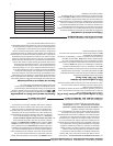
Figure 4 – Single Stage or Multi-Stage System (No Heat Pump) with Single Transformer
* Common connection
required for fault or
malfunction indication.
Single
Stage 1
(SS1)
Multi-
Stage 2
(MS2)
O
Energized Constantly
in Cool Mode
B
Energized Constantly
in Heat, Off,
Emergency
Mode
No
Output
Cool
Mode
2nd
Stage
Cool Mode
1st Stage
Blower/
Circulator
Fan Energized
on Call for
Cool (and
Heat if
configured
for Electric
Heat)
No Output
Heat Mode
2nd Stage
Heat
Mode
1st Stage
Optional*
24 Volt
(Com-
mon)
24 Volt
(Hot)
Cool
System
Y
G
W/E
C
L
RC
CLASS II
TRANSFORMER
HOT
24VAC
NEUTRAL
120VAC
24 Volt
(Hot)
Heat
RH
Y2
W2
Jumper
Fault
Indicator
or
System
Malfunction
Switch
Comfort Alert II Module
or Similar System
Malfunction Module
O/B
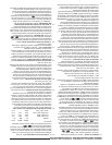
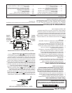
Figure 5 – Single Stage or Multi-Stage System (No Heat Pump) with Two Transformers
Single
Stage 1
(SS1)
Multi-
Stage 2
(MS2)
No
Output
Cool
Mode
2nd
Stage
Cool Mode
1st Stage
Blower/
Circulator
Fan Energized
on Call for
Cool (and
Heat if
configured
for Electric
Heat)
No Output
Heat Mode
2nd Stage
Heat
Mode
1st Stage
Optional
24 Volt
(Com-
mon)
Fault
Indicator
(NOT
USED)
24 Volt
(Hot)
Cool
System
Y
G
W/E
C
L
RC
CLASS II
TRANSFORMER
HOT
24VAC
NEUTRAL
120VAC
24 Volt
(Hot)
Heat
RH
120VAC
Remove Jumper Wire
between RH & RC
HOT
24VAC
NEUTRAL
CLASS II
TRANSFORMER
HEATING
COOLING
Y2
W2
Jumper
O/B
O
Energized Constantly
in Cool Mode
B
Energized Constantly
in Heat, Off,
Emergency
Mode
NOTE: If continuous backlight or
hardwired power input are desired but
do not function in both HEAT and COOL
modes, cut the heating transformer 24V
wires and tape off. Connect the neutral
circuit disconnected from the heating
transformer to the neutral circuit of the
cooling transformer. Disconnect the wire
to the RH terminal and install a jumper
between RH and RC. Depending on
the system requirements, replace the
cooling transformer with a 75VA class II
transformer if needed.
Single Stage
3-wire
Zone Valve
application
Blower/Circulator
Fan Energized
Opens
Valve
(4)
Constant
24 Volt
(Com-
mon)
24 Volt
(Hot)
Cool
System
6
Y
W
C
RC
CLASS II
TRANSFORMER
HOT
24VAC
NEUTRAL
120VAC
24 Volt
(Hot)
Heat
(5)
RH
G
Jumper
Closes
Valve
(6)
Figure 6 – 3-Wire (SPDT) Heat Only Zone Valve Wiring