


3
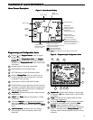
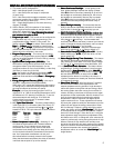
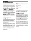
Time of Day
Day of Week
Room
Temperature
System
Switch
Fan
Switch
Indicates when
thermostat is calling
for Heat or Cool
Battery Level Indicator
Indicating the current power level
of the 2 “AA” batteries.
Full power remaining.
Half power remaining.
Change The batteries should be replaced at this time.
Menu key for entering
different modes such as
Cleaning, Configuration, Set
Time and Set Schedule
Enters comfort
temperature settings
into the schedule
Temperature
UP/Down used for
modifying set point
as well as to
navigating the menus
Set Temperature
THERMOSTAT QUICK REFERENCETHERMOSTAT QUICK REFERENCE
THERMOSTAT QUICK REFERENCETHERMOSTAT QUICK REFERENCE
THERMOSTAT QUICK REFERENCE
Home Screen DescriptionHome Screen Description
Home Screen DescriptionHome Screen Description
Home Screen Description
Figure 2 – Home Screen DisplayFigure 2 – Home Screen Display
Figure 2 – Home Screen DisplayFigure 2 – Home Screen Display
Figure 2 – Home Screen Display
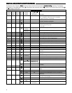
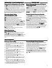
13
"
System OnSystem On
System OnSystem On
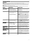
System On" indicates when heating or cooling stage
is energized. "
+2+2
+2+2
+2" also indicates when a second stage
is energized.
14
"
CopyCopy
CopyCopy
Copy" indicates the copy program feature is being
used during programming.
12
"
Call For ServiceCall For Service
Call For ServiceCall For Service
Call For Service" indicates a fault in the heating/
cooling system. It does not indicate a fault in the
thermostat.
11
The words "
Hold AtHold At
Hold AtHold At
Hold At" are displayed when the thermo-
stat is in the
HOLD HOLD
HOLD HOLD
HOLD mode. "
Temporary Hold AtTemporary Hold At
Temporary Hold AtTemporary Hold At
Temporary Hold At" is
displayed when the thermostat is in a temporary
HOLDHOLD
HOLDHOLD
HOLD
mode.
10
"
HoursHours
HoursHours
Hours" and "
DaysDays
DaysDays
Days" displays during steps in installer
configuration.
9
"
Hold UntilHold Until
Hold UntilHold Until
Hold Until" indicates the time when a temporary hold
period will end.
8
Used in programming to set time and in configuration
menu to change selections.
7
CLEAN DISPLAY button allows 30 seconds to wipe off
the display or ADVANCE DAY button for programming.
6
COPY button or INSTALLER CONFIG button.
5
Displays "
Change FilterChange Filter
Change FilterChange Filter
Change Filter" when the system has run
for the programmed filter time period as a reminder
to change or clean your filter.
2
Indicates period of day being programmed.
3
RUN SCHEDULE (run program) button.
4
SET TIME button or HOLD temperature button.
1
Displays and "
Keypad LockoutKeypad Lockout
Keypad LockoutKeypad Lockout
Keypad Lockout" when in keypad
lockout mode.
Displays and "
Temperature LimitTemperature Limit
Temperature LimitTemperature Limit
Temperature Limit" and "
KeypadKeypad
KeypadKeypad
Keypad
LockoutLockout
LockoutLockout
Lockout" when limited range is activated and locked.
Displays only "
Temperature LimitTemperature Limit
Temperature LimitTemperature Limit
Temperature Limit" when limited range
is activated.
Programming and Configuration ItemsProgramming and Configuration Items
Programming and Configuration ItemsProgramming and Configuration Items
Programming and Configuration Items
Figure 3 – Programming & Configuration ItemsFigure 3 – Programming & Configuration Items
Figure 3 – Programming & Configuration ItemsFigure 3 – Programming & Configuration Items
Figure 3 – Programming & Configuration Items
15
A steady "
Cool SavingsCool Savings
Cool SavingsCool Savings
Cool Savings" display indicates the feature
is enabled in the installer menu. A flashing "
CoolCool
CoolCool
Cool
SavingsSavings
SavingsSavings
Savings" display indicates the feature is active.
16
"
RemoteRemote
RemoteRemote
Remote" indicates that the indoor remote temperature
sensor, is being accessed. "
Outdoor RemoteOutdoor Remote
Outdoor RemoteOutdoor Remote
Outdoor Remote" indi-
cates the outdoor remote temperature sensor is being
accessed.
16
15
14
13
12
11
10
9
8
76
54
3
2
1