


2
2 "AA" Batteries
WIRING CONNECTIONSWIRING CONNECTIONS
WIRING CONNECTIONSWIRING CONNECTIONS
WIRING CONNECTIONS
Refer to equipment manufacturers' instructions for specific
system wiring information. After wiring, see CONFIGURA-
TION section for proper thermostat configuration.
For wiring diagrams, see 37-6808.
Wiring diagrams shown are for typical systems and describe
the thermostat terminal functions.
WARNING
!
Thermostat installation and all components of theThermostat installation and all components of the
Thermostat installation and all components of theThermostat installation and all components of the
Thermostat installation and all components of the
control system shall conform to Class II circuits percontrol system shall conform to Class II circuits per
control system shall conform to Class II circuits percontrol system shall conform to Class II circuits per
control system shall conform to Class II circuits per
the NEC code.the NEC code.
the NEC code.the NEC code.
the NEC code.
INSTALLATIONINSTALLATION
INSTALLATIONINSTALLATION
INSTALLATION
Battery LocationBattery Location
Battery LocationBattery Location
Battery Location
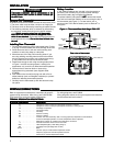
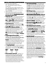
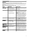
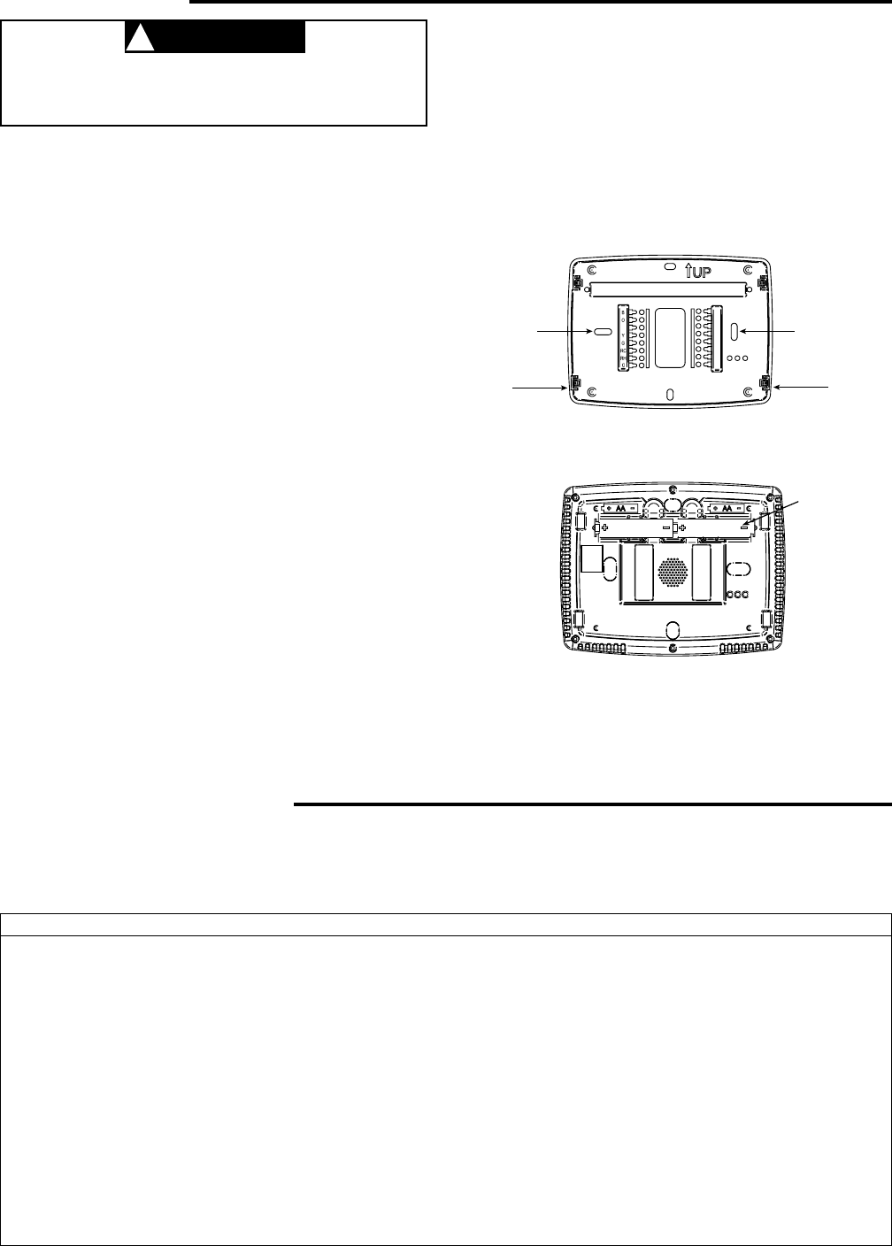
2 "AA" alkaline batteries are included in the thermostat at
the factory with a battery tag to prevent power drainage.
Remove the battery tag to engage the batteries.
To replace batteries, set system to
OFFOFF
OFFOFF
OFF, remove thermostat
from wall and install the batteries in the rear along the top of
the thermostat (see Figure 1). For best results, use a
premium brand "AA" alkaline battery such as Duracell
®
or
Energizer
®
.
Remove Old ThermostatRemove Old Thermostat
Remove Old ThermostatRemove Old Thermostat
Remove Old Thermostat
A standard heat/cool thermostat consists of three basic parts:
1. The cover, which may be either a snap-on or hinge type.
2. The base, which is removed by loosening all captive screws.
3. The switching subbase, which is removed by unscrewing
the mounting screws that hold it on the wall or adapter
plate.
BefBef
BefBef
Bef
oror
oror
or
e re r
e re r
e r
emoemo
emoemo
emo
ving wirving wir
ving wirving wir
ving wir
es fres fr
es fres fr
es fr
om old therom old ther
om old therom old ther
om old ther
mostamosta
mostamosta
mosta
t,t,
t,t,
t,
label each wire with the terminal designation fromlabel each wire with the terminal designation from
label each wire with the terminal designation fromlabel each wire with the terminal designation from
label each wire with the terminal designation from
which it was attachedwhich it was attached
which it was attachedwhich it was attached
which it was attached. Disconnect the wires from the old
thermostat one at a time.
Do not let wirDo not let wir
Do not let wirDo not let wir
Do not let wir
es fes f
es fes f
es f
all bacall bac
all bacall bac
all bac
k intok into
k intok into
k into
the wallthe wall
the wallthe wall
the wall.
Installing New ThermostatInstalling New Thermostat
Installing New ThermostatInstalling New Thermostat
Installing New Thermostat
1. Pull the thermostat body off the thermostat base. Forcing
or prying on the thermostat will cause damage to the unit.
2. Place base over hole in wall and mark mounting hole
locations on wall using base as a template.
3. Move base out of the way. Drill mounting holes. If you
are using existing mounting holes and the holes drilled
are too large and do not allow you to tighten base snug-
ly, use plastic screw anchors to secure the base.
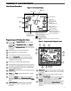
4. Fasten base snugly to wall using mounting holes shown
in Figure 1 and two mounting screws. Leveling is for
appearance only and will not affect thermostat operation.
5. Connect wires to terminal block on base using
appropriate wiring schematic (see diagram sheet
37-6808).
6. Push excess wire into wall and plug hole with a fire re-
sistant material (such as fiberglass insulation) to prevent
drafts from affecting thermostat operation.
7. Carefully line the thermostat up with the base and snap
into place.
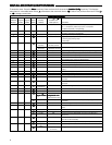
Terminal DesignationTerminal Designation
Terminal DesignationTerminal Designation
Terminal Designation
DescriptionDescription
DescriptionDescription
Description
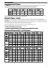
B . . . . . . . . . . . . . . . . . . Changeover valve for heat pump energized constantly in heating
O . . . . . . . . . . . . . . . . . . Changeover valve for heat pump energized constantly in cooling and off
Y2 . . . . . . . . . . . . . . . . . . 2nd Stage Compressor
Y . . . . . . . . . . . . . . . . . . Compressor Relay
G . . . . . . . . . . . . . . . . . . Fan Relay
RC . . . . . . . . . . . . . . . . . . Power for Cooling
RH . . . . . . . . . . . . . . . . . . Power for Heating
C . . . . . . . . . . . . . . . . . . Common wire from secondary side of cooling (Optional). Required for fault indication,
continuous backlight operation or remote temperature sensor operation
L . . . . . . . . . . . . . . . . . . Malfunction indicator for systems with malfunction connection
6 . . . . . . . . . . . . . . . . . . Powered closed 3rd wire for 3-wire zone valve
W/E . . . . . . . . . . . . . . . . . Heat Relay/Emergency Heat Relay (Stage 1)
W2 . . . . . . . . . . . . . . . . . . 2nd Stage Heat (3rd Stage Heat in HP2)
Blank . . . . . . . . . . . . . . . . . Blank
- . . . . . . . . . . . . . . . . . . . Common (DC) for wired remote temperature sensor
S . . . . . . . . . . . . . . . . . . Frequency signal from remote temperature sensor
+ . . . . . . . . . . . . . . . . . . Power (DC) to remote temperature sensor
TERMINAL DESIGNATION DESCRIPTIONSTERMINAL DESIGNATION DESCRIPTIONS
TERMINAL DESIGNATION DESCRIPTIONSTERMINAL DESIGNATION DESCRIPTIONS
TERMINAL DESIGNATION DESCRIPTIONS
Mounting
Hole
Mounting
Hole
Place Level
across
Mounting Tabs
(for appearance only)
Place Level
across
Mounting Tabs
(for appearance only)
+
S
-
W/E
6
L
Y2
W2
Figure 1 – Thermostat Base Multi-Stage 1F95-1277Figure 1 – Thermostat Base Multi-Stage 1F95-1277
Figure 1 – Thermostat Base Multi-Stage 1F95-1277Figure 1 – Thermostat Base Multi-Stage 1F95-1277
Figure 1 – Thermostat Base Multi-Stage 1F95-1277
Rear view of thermostatRear view of thermostat
Rear view of thermostatRear view of thermostat
Rear view of thermostat