


These numbers are approximate and represent operation with a typical system. Actual temperature differentials and
run times may vary widely based on your building and equipment, as well as outdoor temperature conditions.
COMPRESSOR OFF DELAY
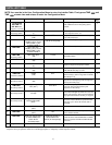
Installer table, step 11 is available if the
fossil fuel kit alternative option (PUMP OFF)
is selected.
This item allows a selection of 0 to 99
seconds, which is the time that the compres-
sor will continue to run after the point that
the auxiliary heat is energized. Running the
compressor after the Auxiliary has started
prevents cool air from creating drafts prior to
the heat exchanger reaching normal tempera-
tures. The factory default value of 60
seconds is typical for most systems. Consult
with your equipment’s manufacturer before
increasing this time.
BALANCE POINT TEMPERATURE
Installer table step 12, bPT, is available only
if the fossil fuel kit option is selected and the
outdoor temperature sensor is used (see the
user menu in the owner manual).
This item allows a selection of 5 to 50° F,
which is the outdoor temperature below
which the thermostat will not energize heat
pump compressor stages. It will use
Auxiliary heat stages (only) until the outdoor
temperature raises 3° above the selected
temperature and then allow compressor
stages to operate. The factory default value
of 35° F is typical for most systems.
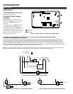
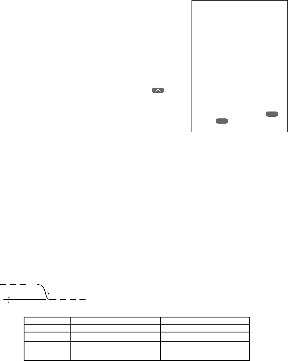
BALANCE POINT
Installer table step 13, bP, is available only if
the fossil fuel kit option is selected and the
outdoor temperature sensor is not used. The
Balance Point influences when second stage
comes on. The factory default creates
approximately 1° F between stages. Increas-
ing the setting decreases the separation
between stages. Decreasing the value
increases stage separation. This adjustment
allows a small change in the operation of
your heat pump system versus your auxiliary
system relative to the thermostat adjustment.
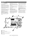
PROGRAMMABLE BLOWER
BALANCE POINT
Installer table step 14, bbP, is available only
when configured for Heat Pump systems, and
wired as shown in Fig. 3.
If the system is running a high percentage of
the time due to cold weather conditions, the
output vent air temperature may be cooler
than normal thus creating a drafty room
condition. This feature will reduce the draft
by lowering the blower speed with the DHM
terminal. The lower speed will make the air
temperature slightly warmer and more
comfortable.
Example: If you want the blower to go to a
lower speed when the system is running
greater than 50% of the time,then reduce the
Blower Balance Point to 50%.
To turn this feature OFF, press
to 99
then press once more to display OFF.
COMPRESSOR LOCKOUT.
(Installer table step 15). This thermostat is
capable of helping to protect the system
against premature compressor failure by
“locking out” the compressor for at least five
minutes after each cycle. When the thermo-
stat is in compressor lockout, the word
COOL will flash on the display. With heat
pump systems, the word HEAT will flash if
the lockout occurs during a heat cycle.
During this period, the compressor will not
be energized.
COMFORT ALERT WITH ACTIVE
PROTECTION.
(Installer table step 16). The Comfort Alert
diagnostics product diagnoses system and
electrical problems in the air conditioning
outdoor systems with single phase Copeland
Scroll compressors. Abnormal conditions are
indicated by flashing ALERT codes on the
yellow LED on the Comfort Alert module.
The flash codes are transmitted to the
thermostat by the Comfort Alert Thermostat
interface module. The Comfort Alert
compatible thermostat displays a CHECK
SYSTEM icon that flashes at the same rate as
the yellow ALERT LED on the Comfort Alert
module. Turn this feature ON to achieve
active protection, enabling the thermostat to
identify certain fault codes when compressor
damage is possible and react to those codes
by turning the compressor off.
Lockout Bypass Option
FOR QUALIFIED SERVICE TECH-
NICIANS’ USE ONLY.
HOMEOWNERS SHOULD NOT USE
THIS FEATURE DUE TO POSSIBIL-
ITY OF EQUIPMENT OR PROP-
ERTY DAMAGE, OR PERSONAL
INJURY.
COMPRESSOR SHORT TERM CYCLE
PROTECTION
If this thermostat has been configured to
provide short-cycle protection, during the
5-minute lockout period the thermostat
will lock out the compressor to allow
head pressure to stabilize. To override
this feature for one cycle while testing
thermostat operation, press SET
TIME
and SET
DAY
buttons at the same time.
If the system has short-cycle protection, this
item should not need to be enabled. How-
ever, if your system does not have short-
cycle protection, turn COMP LOCK ON.
This will protect the compressor from short-
cycling and potential premature compressor
failure.
Note that COMP LOCK OFF permanently
disables compressor lockout. If you need to
temporarily disable compressor lockout,
please see Lockout Bypass Option.
DISABLING AUTOMATIC
CHANGEOVER MODE.
(Installer table step 17). This thermostat, as
configured at the factory, provides automatic
changeover, which allows the thermostat to
switch between heating and cooling to
maintain temperature. In this configuration,
when you press the SYSTEM button, the
thermostat will go through HEAT-OFF-
COOL-AUTO modes (HEAT-EMER-OFF-
COOL-AUTO for heat pumps). Select
HEAT(-EMER)-OFF-COOL to disable the
automatic changeover feature.
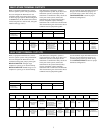
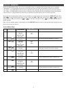
HEATING COOLING
Anticipation Value Cycle Length Differential Temperature Cycle Length Differential Temperature
Shorter 0.4–0.6°F (0.2–0.3°C) N/A1–8 N/A
Longer Shorter9–20 0.6–1.0°F (0.3–0.6°C) 0.6–1.0°F (0.3–0.6°C)
Hydronic Longer21–40 1.0–1.6°F (0.6–0.9°C) 1.0–1.6°F (0.6–0.9°C)
(Continued)
Pump
Stage
Fossil
Auxiliary
Stage
Decreasing
Indoor
temperature
Higher number
Lower number
Stage separation
1˚F at setting 05
7