


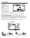
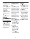
HEAT PUMP TERMINAL OUTPUTS
Refer to equipment manufacturers’ instruc-
tions for specific system wiring information.
You can configure the thermostat for use
with the following heat pump system types:
HEAT PUMP TYPE 1. Single-stage
compressor system; gas or electric backup.
HEAT PUMP TYPE 2. Multi-stage or two-
compressor system; gas or electric backup.
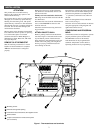
This thermostat is designed to operate a
single-transformer system. If you have a two-
transformer system, cut and tape off one
transformer. If transformer safety circuits are
in only one of the systems, remove the
transformer of the system with NO safety
circuits. If required, replace remaining
transformer with a 75VA Class II transformer.
After disconnecting one transformer, the two
commons must be jumpered together.
Use the terminal output information below to
help you wire the thermostat properly for
your heat pump system type. After wiring,
see CONFIGURATION section for proper
thermostat configuration.
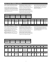
MULTI-STAGE TERMINAL OUTPUTS
Refer to equipment manufacturers’ instruc-
tions for specific system wiring information.
You can configure the thermostat for use
with either multi-stage electric heat systems
or multi-stage gas systems. When configured
for electric heat, the G terminal (blower/fan)
will be energized on a call for heat, using the
installer table (pgs. 5 & 6).
This thermostat is designed to operate a
single-transformer system. If you have a two-
transformer system, cut and tape off one
transformer. If transformer safety circuits are
in only one of the systems, remove the
transformer of the system with NO safety
circuits. If required, replace remaining
transformer with a 75VA Class II transformer.
After disconnecting one transformer, the two
commons must be jumpered together.
Use the terminal output information below to
help you wire the thermostat properly for
your multi-stage system. After wiring, see
CONFIGURATION section for proper
thermostat configuration.
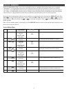
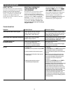
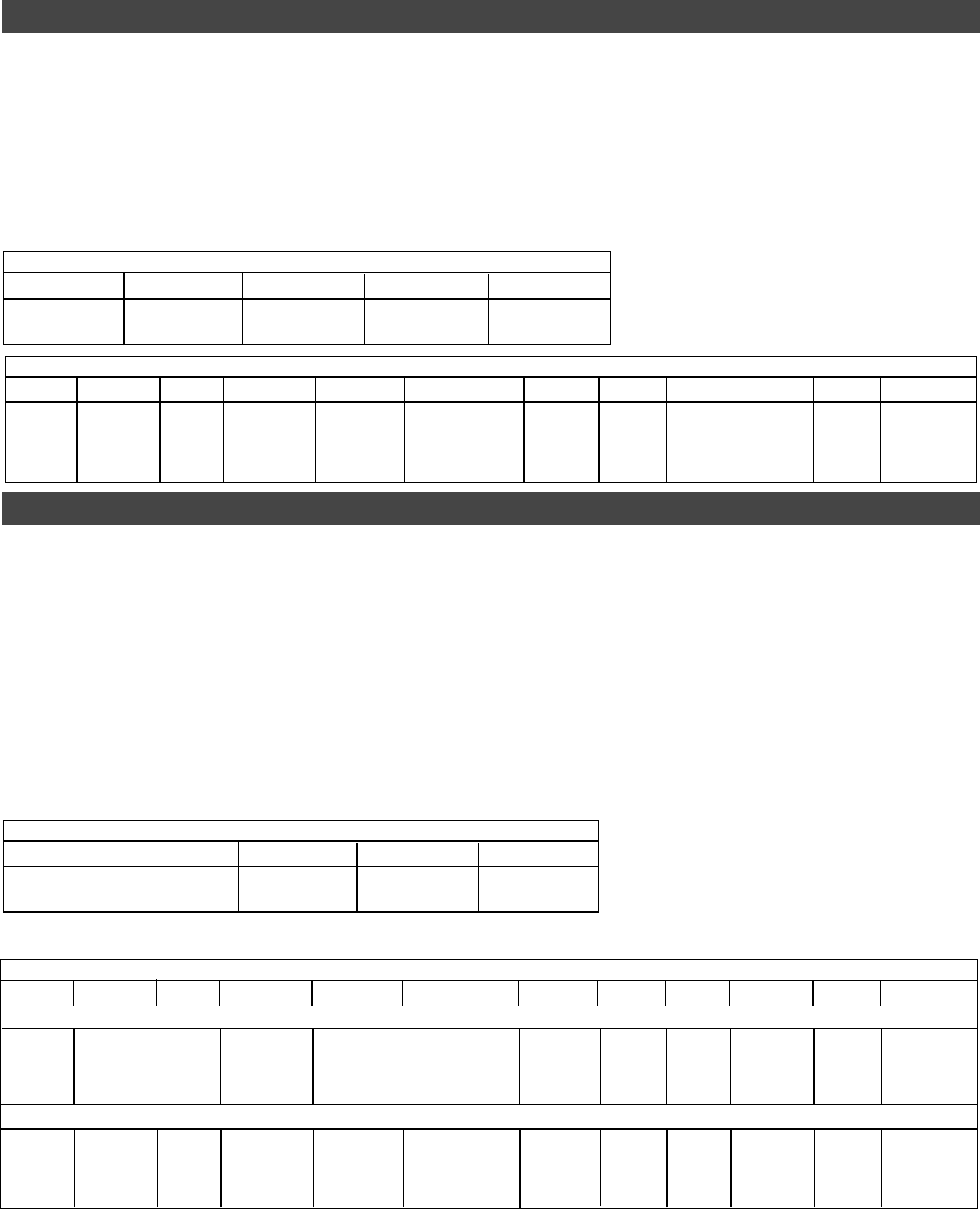
THERMOSTAT TERMINALS (Upper)
LSASBSCOT
Malfunction Light/ Remote Sense A Remote Sense B Remote Sense C Outdoor Sensor
Comfort Alert
Interface Module
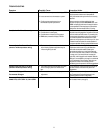
THERMOSTAT TERMINALS (Upper)
LSASBSCOT
Malfunction Light/ Remote Sense A Remote Sense B Remote Sense C Outdoor Sensor
Comfort Alert
Interface Module
3
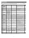
THERMOSTAT TERMINALS (Lower)
SYSTEM C R HM W2 DHM E/W1 Y2 Y1 B O G
Multi-Stage
24 Volt
(Common)
24 Volt
(Hot)
Energizes on a
call for heat if
Humidity setpoint is
above room
humidity.
Heat mode
2nd stage
E2/P switch in the P position,
Energizes on a call for
Dehumidification.
E2/P switch in E2 position,
De-energizes on a
call for Dehumidification.
Heat mode
1st stage
Cool mode
2nd stage
Cool mode
1st stage
Energized in Heat
and Off Mode
Energized in
Cool Mode
Blower/Fan
Energized on
call for Cool
(and Heat if
configured
to Electric Heat).
THERMOSTAT TERMINALS (Lower)
SYSTEM C R HM W2 DHM E/W1 Y2 Y1 B O G
Heat Pump 1
24 Volt
(Common)
24 Volt
(Hot)
Energizes on a
call for heat if
Humidity setpoint is
above room
humidity.
Heat mode
3rd stage,
Emergency Mode
2nd stage
E2/P switch in P position,
Energizes on a call for
Dehumidification.
E2/P switch in E2 position,
De-energizes on a
call for Dehumidification.
Heat mode
2nd stage,
Emergency Mode
1st stage
No Output
Heat and
Cool mode
1st stage
(compressor 1)
Energized in Heat,
Off, Emergency
Mode
Energized in
Cool Mode
Blower/Fan
Energized on
call for Heat and Cool
Single-stage compressor system; gas or electric backup
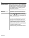
Multi-stage or two compressor system; gas or electric backup
Heat Pump 2
24 Volt
(Common)
24 Volt
(Hot)
Energizes on a
call for heat if
Humidity setpoint is
above room
humidity.
Emergency Mode
2nd stage
E2/P switch in P position,
Energizes on a call for
Dehumidification.
E2/P switch in E2 position,
De-energizes on a
call for Dehumidification.
Heat mode
3rd stage,
Emergency Mode
1st stage
Heat and
Cool mode
2nd stage
(compressor 2)
Heat and
Cool mode
1st stage
(compressor 1)
Energized in Heat,
Off, Emergency
Mode
Energized in
Cool Mode
Blower/Fan
Energized on
call for Heat and Cool