


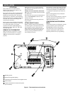
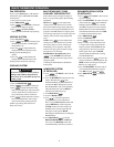
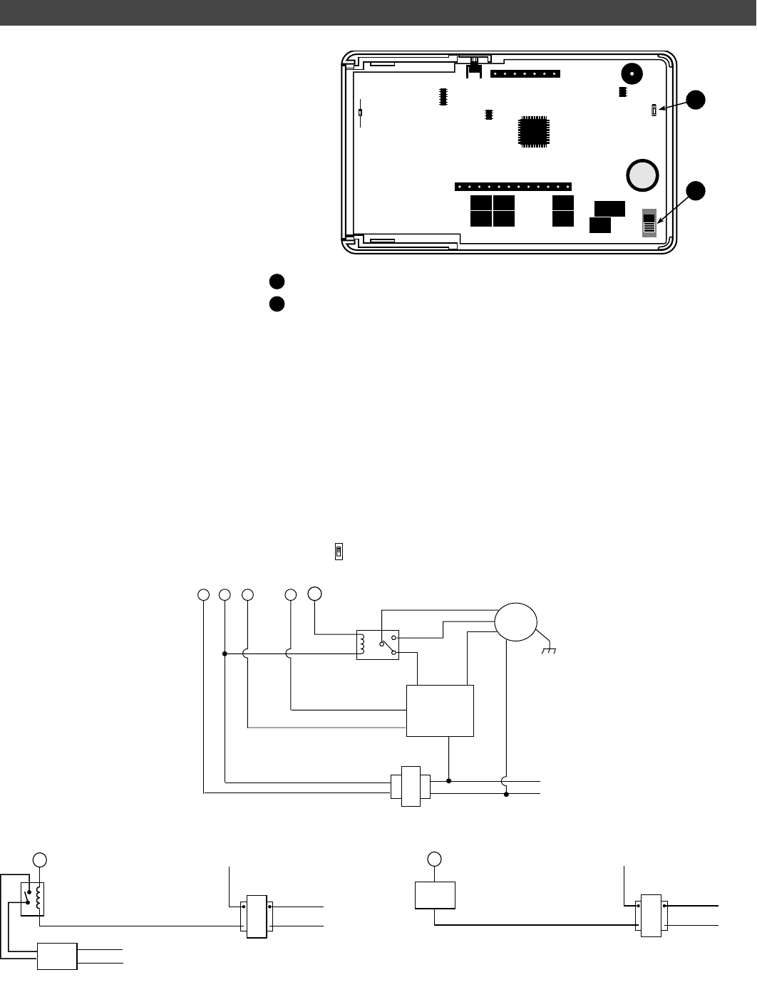
RESET SWITCH
See the Troubleshooting section at the end
of this document for more information about
the function of this switch.
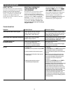
E2/P SWITCH (DHM) TERMINAL
FUNCTION
The E2/P switch is located on the back of
the thermostat body (see fig. 2). This switch
controls how the DHM terminal will be
energized.
1. In the P position (up) the DHM terminal will
be energized on a call for dehumidification.
2. In the E2 position (down) the DHM terminal
will always be energized except on a call for
dehumidification. The switch must be in the E2
position on some electronically controlled
variable speed blower systems.
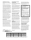
Figure 2. Switch locations on back of thermostat body
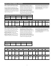
CONFIGURATION
1
2
P
E2
S18
S19
1
2
SWITCHES
HM
R
I
Relay
90-290Q
or equivalent
Humidifier
System
120 VAC
24 VAC
NEUTRAL
HOT
120 VAC
NEUTRAL
HOT
TRANSFORMER
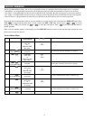
Typical Wiring for 120V Humidifier System
HM
R
I
Humidifier
System
120 VAC
24 VAC
NEUTRAL
HOT
TRANSFORMER
Typical Wiring for 24V Humidifier System
Figure 4. Typical Wiring for 120V Humidifier System
Figure 5. Typical Wiring for 24V Humidifier System
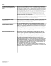
Figure 3. Typical Wiring for Dehumidifier System
DEHUMIDIFICATION WIRING WITHOUT AN ELECTRONICALLY CONTROLLED VARIABLE SPEED BLOWER SYSTEM
FOR SINGLE STAGE COMPRESSOR SYSTEM ONLY
If you have a single stage compressor system see the diagram below. A relay (customer provided) should be installed as shown in Fig. 5 to
switch the fan speed to the next lower speed on a call for dehumidification from the thermostat. The reduction in air flow allows the coil to remove
more humidity from the air. The relay should be rated for blower motor load. Since this configuration reduces the air flow in cooling, the anti-
freeze-up control (White-Rodgers CAFC) or equivalent is recommended. The CAFC prevents the air conditioning coil from freezing due to low
air flow, dirty filters, low refrigerant pressure, etc. The CAFC snaps onto the suction line close to the evaporator coil as possible and breaks the
compressor circuit when the suction line drops below 38°F and re-make the circuit at 46°F.
NOTE: If you have a two stage compressor, the thermostat software will lengthen cycle times for the first stage of cool. The longer cycles will
improve dehumidification while cooling, allowing the DHM terminal not to be used on a two stage compressor system.
24VAC
Heat Fan Speed
Cool Fan Speed
LOW
DHM
CRG
HIGH
MED. HIGH
N.O.
N.C.
3-4 speed
Blower
Motor
COMMON
Y1
Furnace
Control
Module
Customer supplied relay
rated for blower motor load
E2
P
120 VAC
NEUTRAL
TRANSFORMER
HOT
Selecting P - DHM Energizes on call for
Dehumidification
Selecting E2 - DHM Deenergizes on call for
Dehumidification
4
Reset switch
E2/P switch