


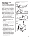
Important: Only a new temperature and pressure relief
valve should be used with your water heater. Do not
use an old or existing valve as it may be damaged or
not adequate for the working pressure of the new water
heater. Do not place any valve between the relief valve
and the tank.
The Temperature & Pressure Relief Valve:
! Must be connected to an adequate discharge line.
! Must not be in contact with any electrical part.
! Must not be rated higher than the working pressure
shown on the data plate of the water heater.
The Discharge Line:
! Must terminate a maximum of 6 inches above a
floor drain or external to the building.
! Must be capable of withstanding 250°F (121°C)
without distortion.
! Must be installed to allow complete drainage of
both the valve and discharge line.
! Must not be smaller than the pipe size of the relief
valve or have any reducing coupling installed in the
discharge line.
! Must not be capped, blocked, plugged, or contain
any valve between the relief valve and the end of
the discharge line.
Solar Installation
If this water heater is used as a solar storage heater or
as a backup for the solar system, the water supply
temperatures to the water heater tank may be in excess
of 120°F. A tempering valve or other temperature
limiting valve must be installed in the water supply line
to limit the supply temperature to 120°F.
Note: Solar water heating systems can often supply
water with temperatures exceeding 180°F and may
result in water heater malfunction.
Electrical Requirements
If you lack the necessary skills required to properly
install the electrical wiring to this water heater, do not
proceed, but have a qualified electrician perform the
installation.
When making the electrical connections, always make
sure:
! The electrical supply has the proper overload fuse
or circuit breaker protection.
! Wire sizes and connections comply with all
applicable codes.
! Wiring is enclosed in approved conduit (if required
by local codes).
! The water heater and electrical supply are properly
grounded.
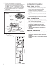
Figure 6 and the wiring diagram can be found on the
next page. Always reference the wiring diagram for the
correct electrical connection. The wiring diagram can
also be found on the inside of the junction box cover.
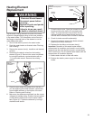
When installing the electrical wiring to the water heater:
1. Shut off the power to the unit.
2. Be sure tank is completely filled with water before
making any electrical connections.
3. Remove junction box cover that is secured by 3
screws. Place the cover aside and view the wiring
diagram on the inside.
4. Connect the electrical supply to the water heater in
accordance with the local utility requirements and
codes. A standard 1/2 inch opening has been made
in the junction box for the conduit connections. Use
approved conduit with copper wires only or Romex.
7
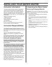
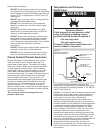
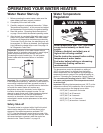
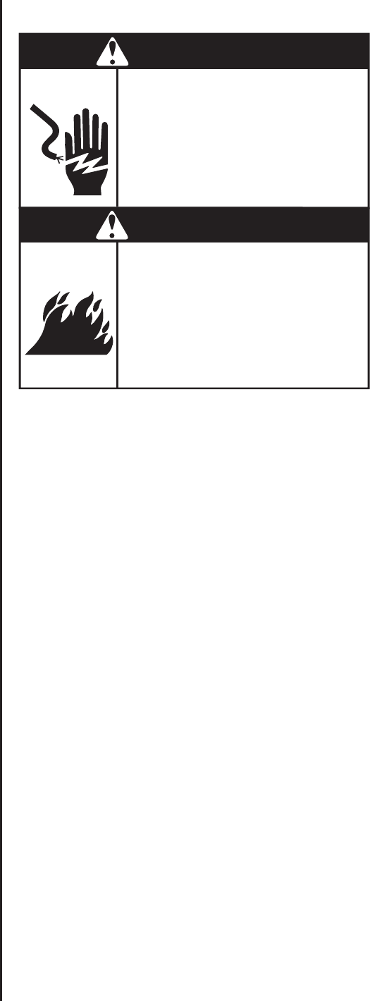
Electric Shock Hazard
Disconnect power before
servicing.
Replace all parts and panels
before operating.
Failure to do so can result in
death or electric shock.
WARNING
Fire Hazard
Use 10 gauge solid copper wire.
Use a UL approved strain relief.
Connect ground wire to green
ground screw.
Failure to do so can result in
death, fire, or electrical shock.
WARNING